
Electron bombardment coating machine

A technology of electron bombardment and coating machine, applied in the field of coating machine, can solve the problems of large heat conduction and heat radiation loss, increase the usage of evaporation materials, reduce the utilization rate of evaporation materials, etc., so as to achieve less loss of heat conduction and heat radiation, and improve the utilization rate. , good consistency

Inactive Publication Date: 2012-10-03
DONGGUAN ANWELL DIGITAL MASCH CO LTD
View PDF5 Cites 10 Cited by
  • Summary
  • Abstract
  • Description
  • Claims
  • Application Information

AI Technical Summary

Problems solved by technology

[0005] However, since the evaporation source device of the existing coating machine is to apply current to the heating plate to make the heating plate generate heat and then heat and evaporate the organic substances in the heating chamber to form evaporation substances to evaporate the substrate, on the one hand, heat conduction and thermal The radiation loss is large, which reduces the evaporation efficiency; on the other hand, the heating of the evaporation material is more dispersed, which increases the usage of the evaporation material correspondingly, thereby reducing the utilization rate of the evaporation material; moreover, the atomic energy of the evaporation material is relatively low when evaporated. Small, so the adhesion of the film layer on the substrate is poor, so it affects the coating quality of the substrate; in addition, it cannot be used for some intolerant metal and non-metal materials (such as gold, tungsten and silicon dioxide, etc.) Evaporation is carried out, so the scope of application of existing coating machines is reduced

Method used


Image

  • Electron bombardment coating machine
  • Electron bombardment coating machine
  • Electron bombardment coating machine

Examples


Embodiment Construction

[0024] In order to describe the technical content and structural features of the present invention in detail, further description will be given below in conjunction with the implementation and accompanying drawings.

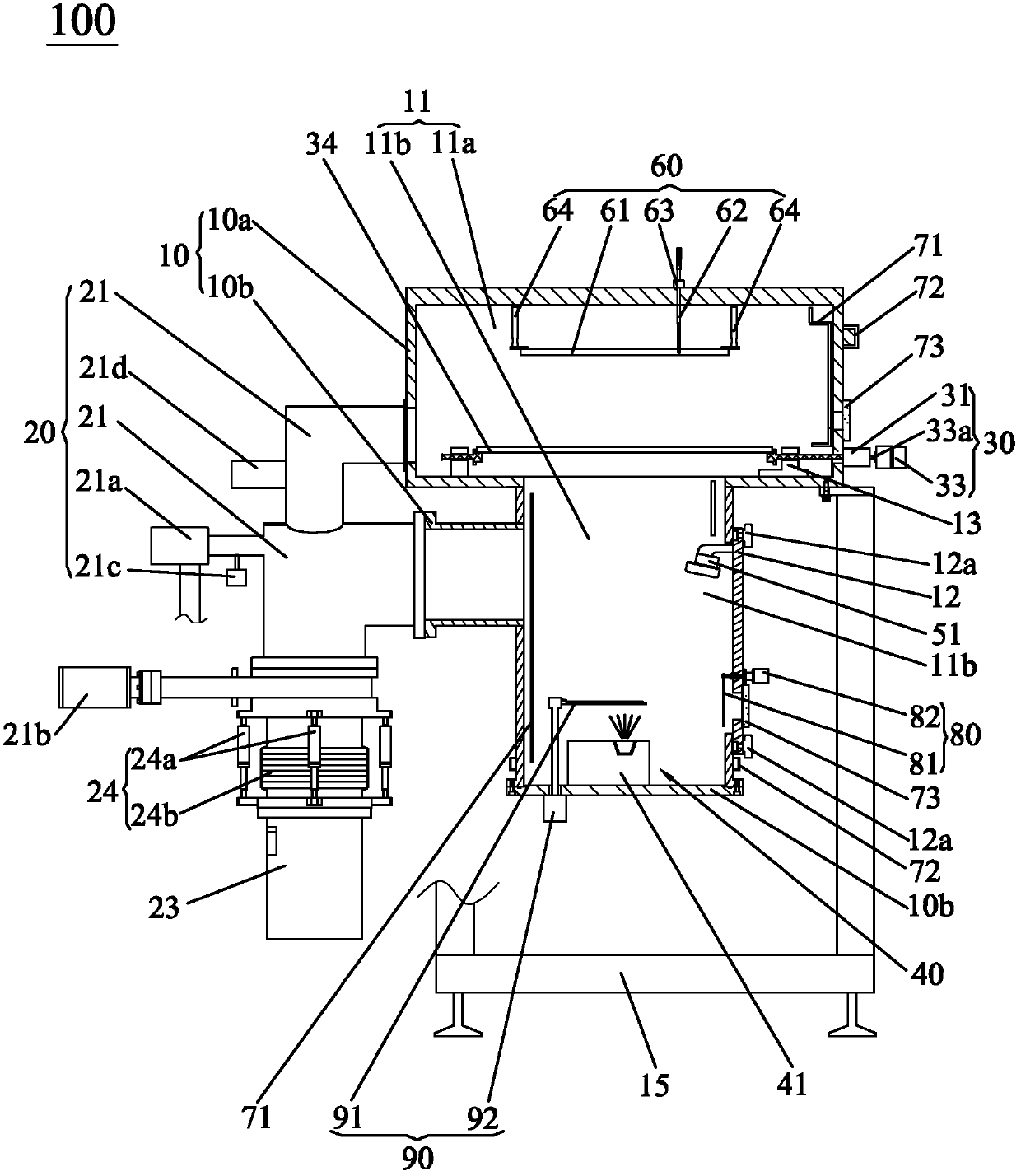
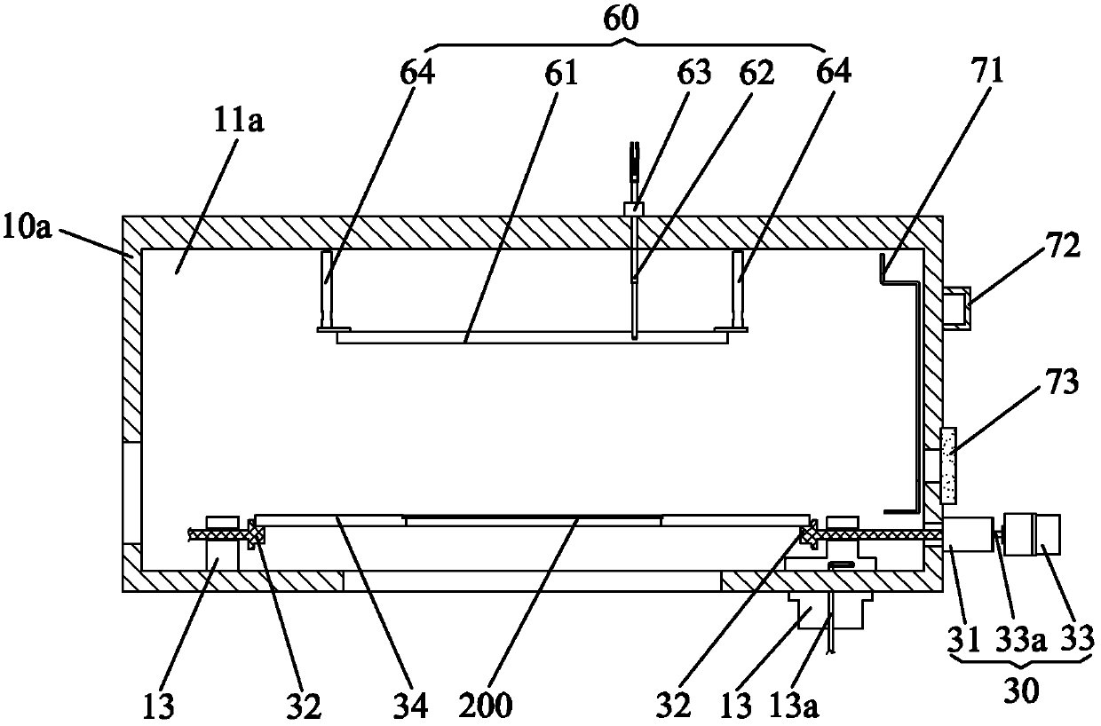
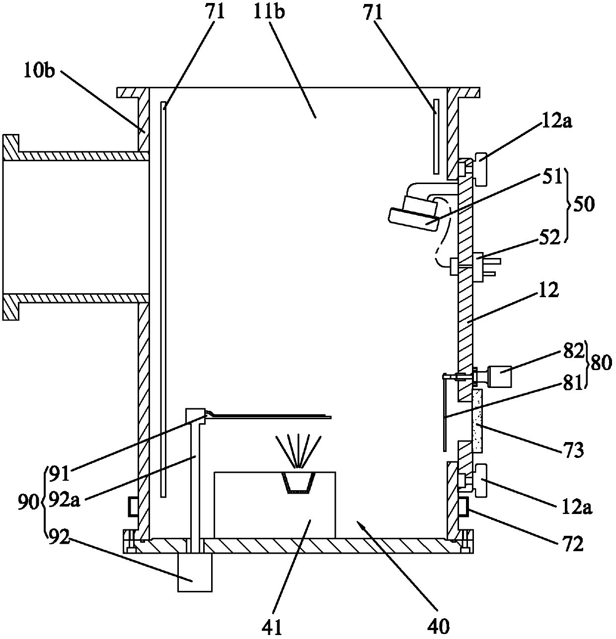
[0025] see Figure 1 to Figure 5 , the electron bombardment coater 100 of the present invention is used for evaporating a thin film layer on a substrate 200, wherein the electron bombardment coater 100 of the present invention includes a cavity 10, a vacuum device 20, a substrate conveying device 30, an evaporation source device 40, a film thickness Monitoring device 50 and controller. A vacuum chamber 11 providing a vacuum environment is opened in the chamber body 10 to create a vacuum environment for the coating of the substrate 200 , and the vacuum pumping device 20 communicates with the vacuum chamber 11 . The substrate conveying device 30 is disposed on the chamber body 10 , and the substrate conveying device 30 is responsible for conveying the substrate 20...


PUM


Abstract

The invention discloses an electron bombardment coating machine which comprises a cavity, an evacuating device, a substrate conveying device, an evaporation source device, a coating thickness monitoring unit and a controller. The cavity is provided with a vacuum cavity communicated with the evacuating device. The substrate conveying device is used for conveying substrates between the outside and the vacuum cavity. The evaporation source device located inside the vacuum cavity below the substrate inside the vacuum cavity comprises a body, an electron gun, deflecting electrodes and an evaporation source carrier. The electron gun and the evaporation source carrier are respectively arranged in the body of the evaporation source device. The deflecting electrodes are located between the electron gun and the evaporation source carrier. The top of the body is provided with an electron gun ejection outlet and a sputtering opening. The coating thickness monitoring unit comprises a coating thickness monitor which is located inside the vacuum cavity and between the evaporation source device and one substrate. The controller is respectively electrically connected with the evacuating device, the electron gun, the deflecting electrodes, the substrate conveying device and the coating thickness monitor. By the electron bombardment coating machine, evaporating efficiency and material utilization rate can be improved to meet the requirement for automation.

Description

technical field [0001] The invention relates to a coating machine suitable for coating a substrate in an organic light emitting diode, in particular to an electron bombardment coating machine for coating a substrate in an organic light emitting diode. Background technique [0002] Thin sheets such as glass substrates have been widely used in the manufacture of LCD-TFT displays, organic light-emitting display device (OLED) panels, solar panels, and the like. In such applications, thin films are mostly deposited on clean glass. The process for such large glass substrates usually involves the implementation of multiple sequential steps, including chemical vapor deposition (CVD), physical vapor deposition (PVD), organic substances Evaporation, magnetron sputtering deposition or etching processes. [0003] Since the process requirements of the above-mentioned processes are relatively strict, especially the evaporation process of organic substances, not only needs to be carried o...

Claims


Application Information

Patent Timeline
IPC IPC(8): C23C14/30
Inventor 叶宗锋范继良刘惠森
Owner DONGGUAN ANWELL DIGITAL MASCH CO LTD
Learn More