Pneumatic tire

A technology of pneumatic tires and tires, applied in tire parts, tire tread/tread pattern, transportation and packaging, etc., can solve the problems of excessive rigidity reduction of small block g, easy concentration of wear, etc., to prevent uneven wear , Improve the performance on snow and reduce the effect of poor rigidity

Active Publication Date: 2012-10-03
SUMITOMO RUBBER IND LTD
View PDF7 Cites 14 Cited by
  • Summary
  • Abstract
  • Description
  • Claims
  • Application Information

AI Technical Summary

Problems solved by technology

[0006] However, in the conventional tire a, since the same number of sipes s are provided in each block g regardless of the size of the block g, the rigidity of the small block g decreases excessively, and wear tends to concentrate. question

Method used


Image

  • Pneumatic tire
  • Pneumatic tire
  • Pneumatic tire

Examples


Embodiment

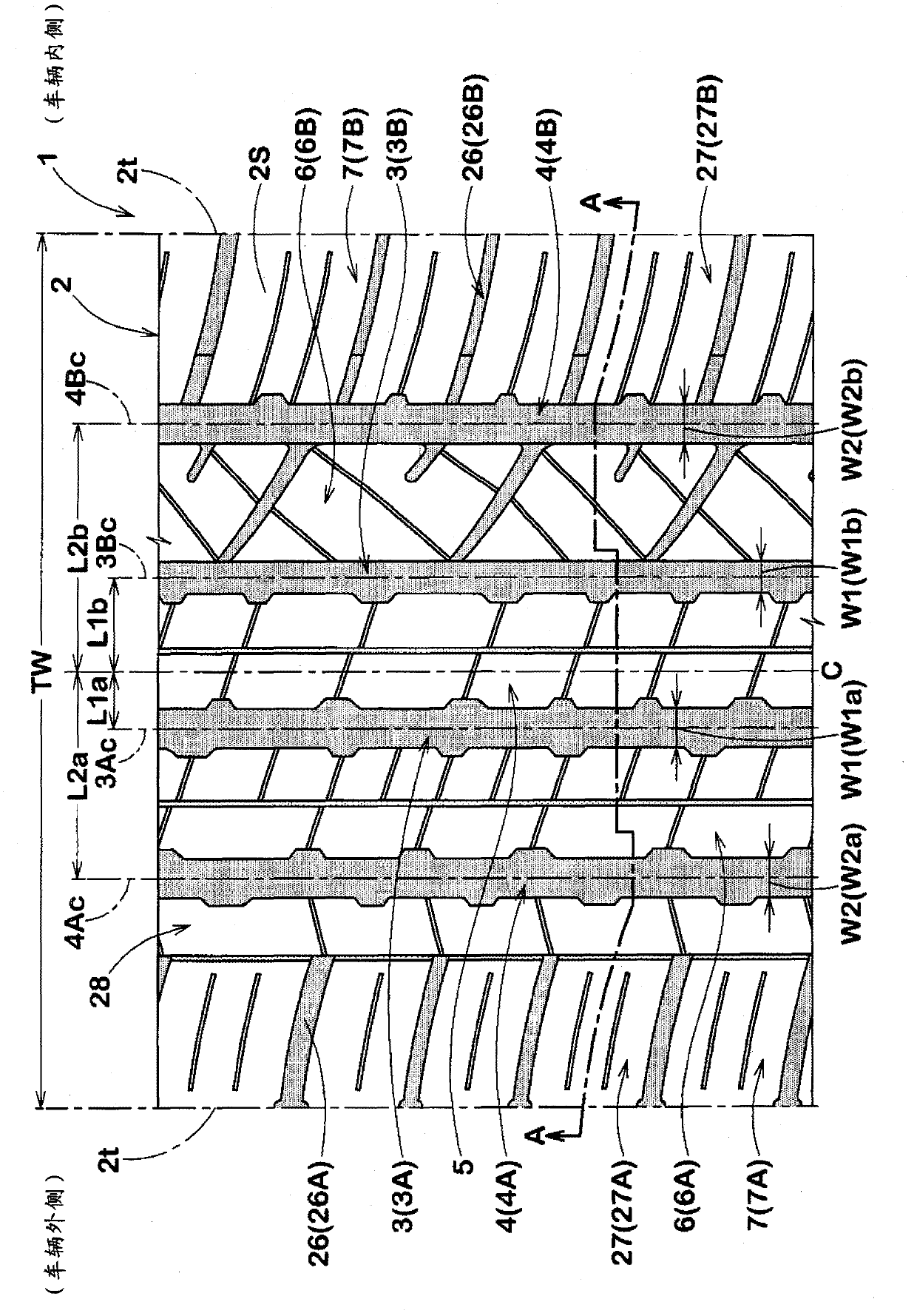
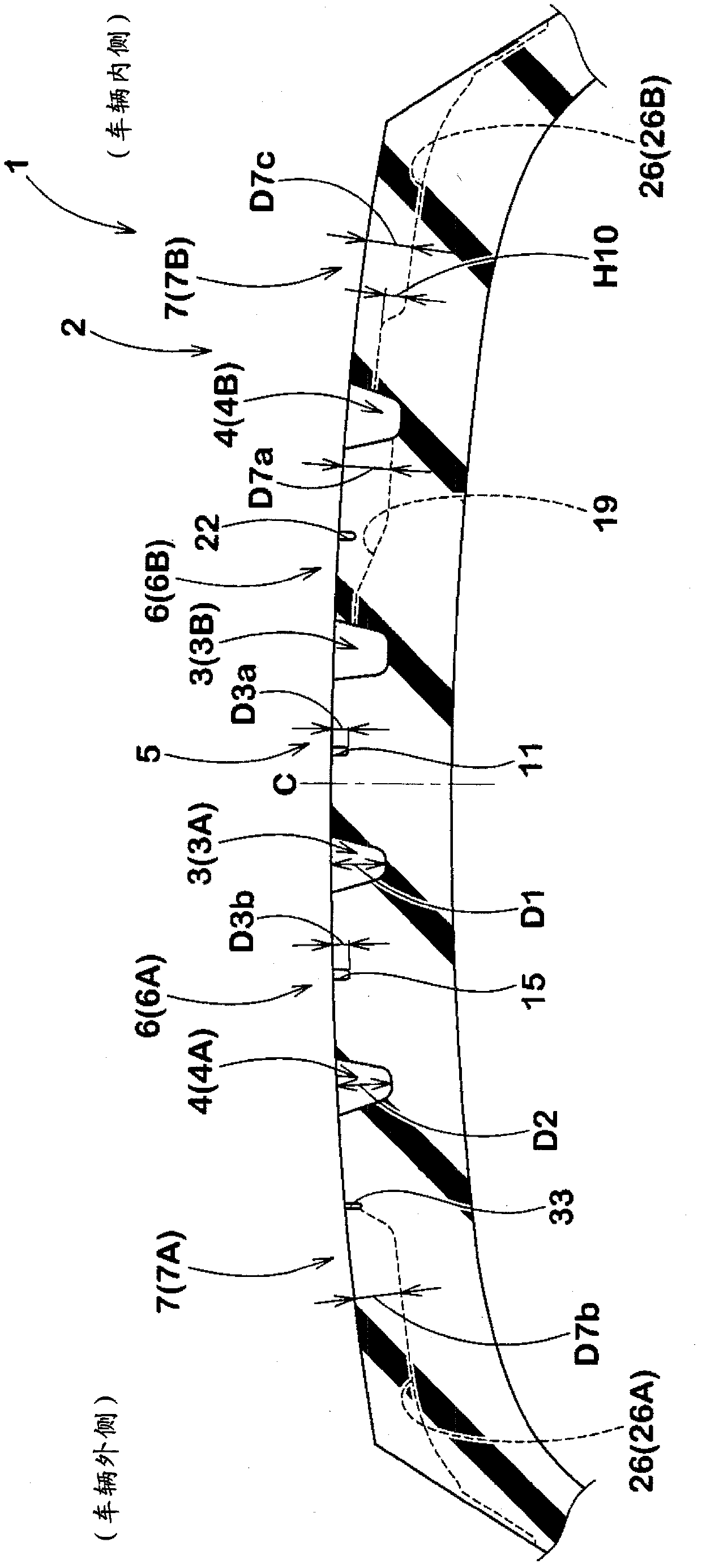
[0101] manufacturing form figure 1 The tires having the basic structure shown in Table 1 and the tires having the block elements and shoulder sipes shown in Table 1 were evaluated for their performance. Among them, the common specifications are as follows.

[0102] Tire size: P235 / 60R18

[0103] Rim size: 18×7.5

[0104] Tread width TW: 198mm

[0105] Central longitudinal groove:

[0106] Groove depth D1: 8.2mm

[0107] Groove width W1a of the outer central longitudinal groove: 8.7mm, distance L1a: 12.45mm

[0108] Groove width W1b of inner central longitudinal groove: 7.1mm, distance L1b: 20.85mm

[0109] Shoulder longitudinal groove:

[0110] Groove width W2: 8.7mm

[0111] Groove depth D2: 8.2mm

[0112] Distance L2a of outer shoulder longitudinal groove: 45.85mm

[0113] Distance L2b of inner shoulder longitudinal groove: 54.7mm

[0114] Central auxiliary groove, outer middle auxiliary groove:

[0115] Groove width W3a, W3b: 1.3mm, groove depth D3a, D3b: 2.5mm...


PUM


Abstract

A pneumatic tire (1) has a shoulder land zone provided with lateral grooves (26) arranged at variable pitches in the tire circumferential direction and extending at an angle of not more than 30 degrees with respect to the tire axial direction. The domains defined between the shoulder lateral grooves include a smallest domain (31S) having the smallest circumferential length and a largest domain (31L, 41L) having the largest circumferential length. The domains are each provided with at least one sipe (32) extending at an angle of not more than 30 degrees with respect to the tire axial direction. The number of the sipe(s) in the smallest domain (31S, 41S) is less than the number of the sipes in the largest domain (31L, 41L).

Description

technical field [0001] The present invention relates to a pneumatic tire capable of maintaining performance on icy and snowy roads and improving uneven wear resistance. Background technique [0002] known as Figure 7 Shown is a pneumatic tire (also referred to as an all-season tire) a that improves not only running performance on paved roads but also running performance on icy and snowy roads and the like. Such a tire a is provided with a block row in which blocks g divided by shoulder lateral grooves u are arranged in the tire circumferential direction in the shoulder region of the tread portion b. In addition, a sipe s extending in the tire axial direction is formed on the block g. [0003] This type of block g can bite into snowy roads to obtain traction, and in addition, on icy roads, it can obtain greater friction through the edges of the sipe s. Related techniques are as follows. [0004] Patent Document 1: Japanese Patent Laid-Open No. 2001-219718 [0005] Howeve...

Claims


Application Information

Patent Timeline
Patent Type & Authority Applications(China)
IPC IPC(8): B60C11/03B60C11/12
CPCB60C11/11B60C11/0306B60C2011/1254B60C11/1369B60C2011/0346B60C11/12B60C2011/0365B60C11/01B60C11/03B60C11/0304
Inventor 林浩二
Owner SUMITOMO RUBBER IND LTD
Why Eureka
Try Eureka