Eureka AIR delivers breakthrough ideas for toughest innovation challenges, trusted by R&D personnel around the world.

Full-view probing robot monobody for complex region at ferromagnetic environment

A robot and environment technology, applied in the direction of manipulators, program-controlled manipulators, manufacturing tools, etc., can solve problems such as difficulty in realization, motion stagnation, and inability to move, so as to ensure motion stability, strong environmental adaptability, and efficient adjustment of step distance Effect

Inactive Publication Date: 2012-10-03
BEIHANG UNIV
View PDF6 Cites 5 Cited by
  • Summary
  • Abstract
  • Description
  • Claims
  • Application Information

AI Technical Summary

Problems solved by technology

[0004] (1) Wheeled movement: The DC motor drives the wheels to move, and the control is more convenient, but it cannot move on a plane with a large angle, and it cannot move well in an environment with limited movement space. The fatal flaw is that when the movement encounters When reaching a ravine, will stall movement
[0005] (2) Bipedal movement: The advantage of bipedal movement is that it is fast and imitates human gait. Through the adjustment of gait, it has certain adaptability. However, the difficulty of bipedal movement lies in the adjustment of the center of gravity of the body. Due to the difficulty of adjusting the center of gravity Large, so it is difficult to balance speed while ensuring stability
[0006] (3) All kinds of bionic movements: imitate the movements of various creatures in the biological world, and have strong environmental adaptability, but it is difficult to realize. Often, independent mechanical design is required to achieve certain specific movements, and general-purpose devices cannot be used. very high

Method used


Image

  • Full-view probing robot monobody for complex region at ferromagnetic environment
  • Full-view probing robot monobody for complex region at ferromagnetic environment
  • Full-view probing robot monobody for complex region at ferromagnetic environment

Examples


Embodiment Construction

[0029] The present invention will be further described in detail below in conjunction with the accompanying drawings.

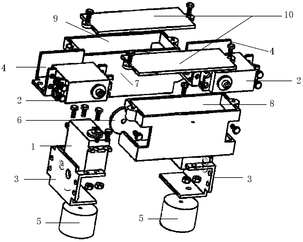
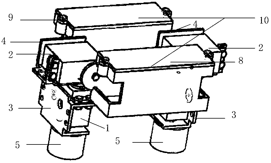
[0030] The present invention proposes a single panorama detection robot in complex ferromagnetic environment, such as figure 1 and figure 2 As shown, it includes the two-foot part and the main body part. The two-foot part includes two parts, the left and right feet. The connection methods are exactly the same. After the connection, the left and right feet are mirror-symmetrical, and the structure of the steering gear bracket B4 in the left and right feet is mirror-symmetrical, as shown in Figure 3-5 . Both the steering gear bracket A3 and the steering gear bracket B4 are L-shaped bracket structures, the steering gear A1 is connected to the bracket frame of the steering gear bracket A3 through M3 bolts, and the steering gear B2 is connected to the steering gear through M3 bolts In the bracket frame of the bracket B4, the bottom of the short bracket of the...


PUM


Abstract

The invention provides a full-view probing robot monobody for a complex region at the ferromagnetic environment, which belongs to the technical field of a probing robot moving with multiple degrees of freedom. The robot monobody comprises left and right feet and a main body; each of the left and right feet comprises a steering engine A, a steering engine B, a steering support A, a steering support B and an electromagnet; and the left foot and the right foot adopt the same connecting way and are in mirror symmetry when in assembly. The main body comprises a front cross beam and a rear cross beam; a battery box and a main control case are respectively processed at the outer side of each of the front cross beam and the outer side of the rear cross beam; and the main control case is internally provided with a single chip microcomputer. The robot monobody provided by the invention has a creative and simple mechanical structure with double coupling and 4 degrees of freedom and is high in reliability; and the robot monobody has various modes of motion, can rapidly realize the switchover between rolling motion and feet motion, can efficiently adjust gait and step pitch, can accurately and rapidly realize adjustment of moving direction in the range of 0-360degree, can realize stereoscopic motion in total space and can achieve multiple objectives of crossing obstacles and ravines, turning corners and changing directions.

Description

technical field [0001] The invention relates to a single panorama detection robot in complex ferromagnetic environment areas, and belongs to the technical field of multi-degree-of-freedom motion detection robots. Background technique [0002] In modern production and life, there are a large number of complex ferromagnetic environments, such as rolling mills, TV towers, power generation towers, steel bridges, steel structure workshops, etc. In these complex ferromagnetic environments, traditional robots are inefficient and cannot be fully utilized. ferromagnetic environment. Electromagnet is a commonly used component in ferromagnetic environment. After being connected with direct current, it can generate a large suction force and is easy to control. As an actuator, the steering gear has the advantages of simple control, simple wiring, and precise angle control. However, as a mechanical element, there is inevitably a certain amount of space difference, and the angle range is ...

Claims


Application Information

Patent Timeline
IPC IPC(8): B25J9/00B25J19/02B25J19/04
Inventor 张益鑫王少萍王冬马岳轩
Owner BEIHANG UNIV
Why Eureka
Eureka Blog
Learn More