Plasma Cutting Linear Bevel Swing Device

A swing device and plasma technology, applied in the direction of plasma welding equipment, auxiliary equipment, welding/cutting auxiliary equipment, etc., can solve the problems of troublesome adjustment, changing the position of the cutting torch, and cutting can not be adjusted at will, so as to achieve low equipment manufacturing cost , High work efficiency, good cutting quality

Active Publication Date: 2014-10-15
WUXI HUALIAN PRECISION MACHINERY
View PDF5 Cites 0 Cited by
  • Summary
  • Abstract
  • Description
  • Claims
  • Application Information

AI Technical Summary

Problems solved by technology

[0002] In the prior art, the linear bevel of plasma cutting mostly adopts three-flame cutting torch or tilting the torch to the required angle for cutting. The above two cutting methods are manually adjusted, which is troublesome to adjust, and it takes The position of the torch will change, so it cannot be adjusted at will during cutting

Method used


Image

  • Plasma Cutting Linear Bevel Swing Device
  • Plasma Cutting Linear Bevel Swing Device

Examples


Embodiment Construction

[0015] Below in conjunction with specific accompanying drawing and embodiment the present invention will be further described:

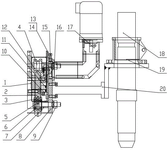
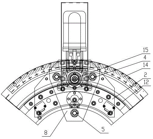
[0016] Such as figure 1 and figure 2 As shown, the arc-shaped guide rail 2 is installed on the bottom plate 1 of the plasma cutting linear groove swing device of the present invention, and the arc-shaped rack 12 is installed on the arc-shaped guide rail 2. The arc-shaped guide rail 2 and the arc-shaped rack 12 have the same center, and the arc The upper and lower guide rail surfaces of the guide rail 2 are V-shaped at 90°. There are three installation holes on the rotating plate 8, two fixed shafts 4 on the top, and an eccentric shaft 5 installed at the center of symmetry below, arranged in an inverted "pin" shape, and the three V-shaped cross-section rollers 3 are installed on the fixed shaft through bearings 6. On the shaft 4 and the eccentric shaft 5, the distance between the rotating plate 8 and the arc guide rail 2 is trimmed through the bush...


PUM


Abstract

The invention relates to a plasma cutting linear groove swinging device. Concentric arc racks are mounted on an arc guide rail; upper and lower guide rail surfaces of the arc guide rail are V-shaped; a rotating plate is matched with the upper and lower guide rail surfaces of the arc guide rail through three V-shaped section rollers, which are shaped like a reversed delta; a speed reducing motor is mounted on a bracket; a gear engaged with the arc rack is mounted on an output shaft of the speed reducing motor; a clamper seat for clamping a plasma cutting torch is connected to the rotating plate by a connecting bracket; a connecting line between a cutting point after being clamped by the plasma cutting torch and the circle center of the arc guide rail is horizontal, and the cutting point and the circle center of the arc guide rail are positioned on the same vertical plane. The plasma cutting linear groove swinging device provided by the invention can be electrically controlled according to requirements on angles, such as grooves; the rotation center of the rotated cutting torch is always kept invariable without using the system to compensate the offset of the rotation center, so that high automation degree, accuracy for positioning the angle, high working efficiency and good cutting quality are achieved. According to the invention, the electric control can be achieved by a common motor, so that equipment manufacturing cost is low.

Description

technical field [0001] The invention relates to the technical field of plasma cutting equipment, in particular to a linear groove swing device for plasma cutting with an automatic adjustment function. Background technique [0002] In the prior art, the linear bevel of plasma cutting mostly adopts three-flame cutting torch or tilting the torch to the required angle for cutting. The above two cutting methods are manually adjusted, which is troublesome to adjust, and it takes The position of the torch will change, so it cannot be adjusted at will during cutting. Contents of the invention [0003] The purpose of the present invention is to overcome the above disadvantages, thereby providing a plasma cutting linear bevel swing device with a reasonable and compact structure, which is easy to operate and can automatically control the angle. [0004] Main technical scheme of the present invention is as follows: [0005] A plasma cutting linear bevel swing device, the arc-shaped...

Claims


Application Information

Patent Timeline
Patent Type & Authority Patents(China)
IPC IPC(8): B23K37/02B23K10/00
Inventor 吴美琴邵燕瑛董立锋范彬陆志远
Owner WUXI HUALIAN PRECISION MACHINERY
Why Eureka
Try Eureka