
Solar microwave oven

A microwave oven and solar energy technology, applied in the field of microwave ovens, can solve the problems of increasing the difficulty of installation and wiring, increasing the cost of microwave ovens, etc., and achieve the effects of simple and reasonable structure, wide application range and high energy efficiency ratio

Inactive Publication Date: 2012-09-26
GUANGDONG MIDEA KITCHEN APPLIANCES MFG CO LTD
View PDF5 Cites 1 Cited by
  • Summary
  • Abstract
  • Description
  • Claims
  • Application Information

AI Technical Summary

Problems solved by technology

The solar cells of this structure are arranged outside the microwave oven, which increases the difficulty of installation and wiring; and the exhaust fan and the turntable motor are driven by AC, and a part of the direct current generated by the solar cell needs to be converted into AC for use by the exhaust fan and the turntable motor. Raise the cost of microwave ovens

Method used


Image

  • Solar microwave oven
  • Solar microwave oven
  • Solar microwave oven

Examples


no. 1 example

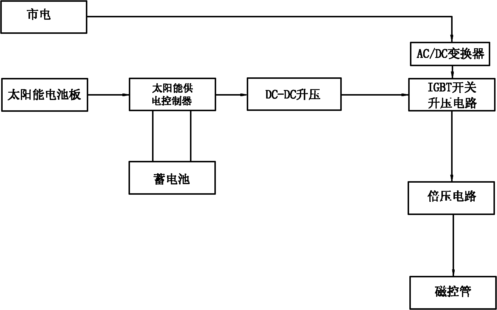
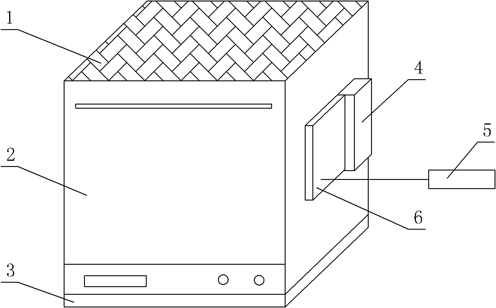
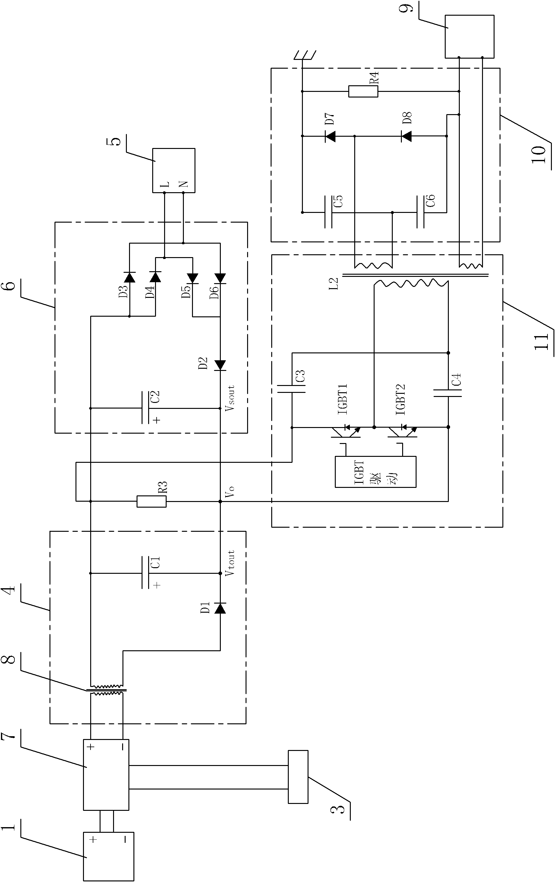
[0022] see Figure 1-Figure 3 , the solar microwave oven includes a battery 3 that provides power for the magnetron 9 of the microwave oven 1, the battery 3 is connected to the solar panel 1 through a solar power supply controller 7; the solar power supply controller 7 is also electrically connected to the magnetron 9 through a drive circuit connect. The solar panel 1 is located at the top of the outer cover of the microwave oven 2 ; the storage battery 3 is located at the bottom of the microwave oven 2 .

[0023] The driving circuit includes a DC / DC converter 4, an IGBT switch boost circuit 11 and a voltage doubler circuit 10; Tube 9 is electrically connected.

[0024] The DC / DC converter 4 includes a DC-DC step-up 8, a diode D1 and a capacitor C1, wherein the cathode of the diode D1 is connected to the anode of the capacitor C1. The IGBT switch boost circuit 11 includes an IGBT driver, IGBT1, IGBT2, a resonant capacitor C3, a resonant capacitor C4 and a high-frequency hig...

no. 2 example

[0029] see Figure 4 The storage battery 3 is plate-shaped, and is movably arranged on the top surface of the outer cover of the microwave oven 2; the solar battery panel 1 is arranged on the top surface of the storage battery 3, and is connected with the storage battery 3 as a whole, so as to be easily removed and charged outdoors. Other unmentioned parts are the same as the first embodiment.

no. 3 example

[0031] see Figure 5 , The solar panel 1 is arranged on the top of the outer cover of the microwave oven 2 ; the battery 3 is arranged on the back of the microwave oven 2 . Other unmentioned parts are the same as the first embodiment.


PUM


Abstract

A solar microwave oven comprises a storage battery which provides power for magnetron of the microwave oven. The storage battery is connected with a solar cell panel through a solar power supply controller. The solar power supply controller is electrically connected with the magnetron through a driving circuit. The solar cell panel and the storage battery are arranged on the microwave oven. The solar cell panel and the storage battery of the solar microwave oven of the invention are arranged on the microwave oven. A user can conveniently install the solar cell panel and the storage battery. An extra lead does not need to be connected. When the microwave oven does not work, a current generated by the solar cell panel can be stored in the storage battery. When the microwave oven works, the storage battery power can be used preferentially. Besides, in order to avoid a situation that a microwave oven load can not be satisfied because the solar cell output power is not enough, an electric supply is added. A solar cell panel circuit and an electric supply circuit form a parallel circuit so as to realize direct current side grid connection. A structure is simple and reasonable. Energy saving, low carbon and environmental protection can be achieved. Usage is convenient. An energy efficiency ratio is high. An application range is wide.

Description

technical field [0001] The invention relates to a microwave oven, in particular to a solar microwave oven. Background technique [0002] At present, with the high efficiency and convenience of microwave ovens, their promotion has become more and more widespread, and they have entered different consumer fields: household, commercial, and medical. Microwave ovens are generally powered by municipal electricity. As we all know, the supply of municipal electricity generally depends on hydroelectric power generation and coal-fired power generation, which wastes a lot of natural energy and brings a lot of pollution to the environment. [0003] Chinese Patent Document No. CN101922748A disclosed on December 22, 2010 a microwave oven using a solar photovoltaic power generation system as a power supply. Sunlight irradiates solar cells to generate direct current. spare. When the switch of the microwave oven is turned on, the DC input inverter is converted into AC power, and the AC pow...

Claims


Application Information

Patent Timeline
Patent Type & Authority Applications(China)
IPC IPC(8): H05B6/04H02N6/00H02J7/00H02S10/20
CPCY02B40/00Y02E10/50Y02E70/30
Inventor 唐相伟欧军辉冯文梯
Owner GUANGDONG MIDEA KITCHEN APPLIANCES MFG CO LTD
Learn More