
Color light mixing method, color light mixing device and small-sized projecting system having such color light mixing device

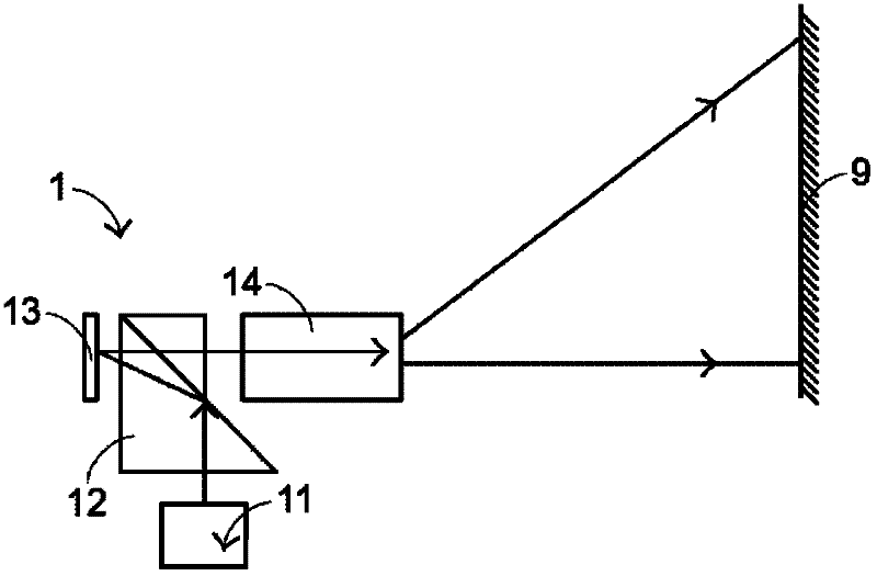
A technology of a light mixing device and a projection system, which is applied in the fields of light mixing methods and light mixing devices

Inactive Publication Date: 2012-09-26
MIN AIK TECH
View PDF9 Cites 2 Cited by
  • Summary
  • Abstract
  • Description
  • Claims
  • Application Information

AI Technical Summary

Problems solved by technology

[0007] According to the above, the existing light mixing device still has considerable room for improvement

Method used


Image

  • Color light mixing method, color light mixing device and small-sized projecting system having such color light mixing device
  • Color light mixing method, color light mixing device and small-sized projecting system having such color light mixing device
  • Color light mixing method, color light mixing device and small-sized projecting system having such color light mixing device

Examples


Embodiment Construction

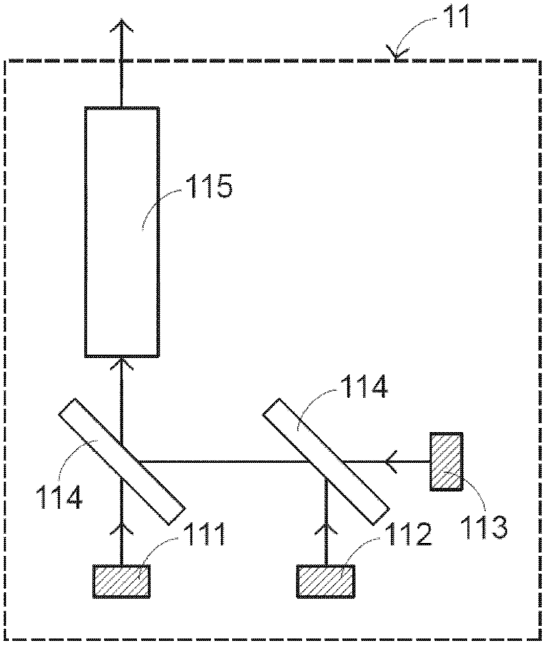
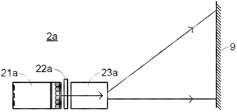
[0100] The light mixing method and the light mixing device provided by the present invention can be applied to the small projection system of the four implementations described below, but this does not limit the scope of application of the present invention, wherein the light mixing method and the light mixing device will It will be described in detail later.

[0101] see Figure 3A, which is a schematic structural diagram of the first embodiment of the small projection system of the present invention. The small projection system 2a includes a light mixing device 21a, a display element 22a, and an optical lens 23a, and the display element 22a is disposed between the light mixing device 21a and the optical lens 23a, and the light mixing device 21a is used to provide light to illuminate the image to present The display element 22a is used to project and magnify the image presented on the display element 22a onto a projection surface 9 through the optical lens 23a. In this embo...


PUM


Abstract

A color light mixing device, a color light mixing method and a small-sized projecting system using the color light mixing device are provided. The color light mixing device includes a tube structure, a plurality of light-emitting units, a reflective polarizer and a microlens assembly. The light-emitting units are located at an inlet end of the tube structure. The reflective polarizer is located at the other end of the tube structure. The microlens assembly is arranged between the light-emitting units and the reflective polarizer. By the color light mixing device, the light beams with a single polarization state are homogenized and outputted to a microdisplay element of the small-sized projecting system. By an optical projection lens assembly of the small-sized projecting system, an image shown on the microdisplay element is projected onto a screen.

Description

technical field [0001] The present invention relates to a light mixing method and a light mixing device, in particular to a light mixing method applied to a small projection device, a light mixing device and a small projection system using the light mixing device. Background technique [0002] In daily life, projection systems are often used to magnify graphic or image data on the projection surface, making users more visually comfortable when watching, and electronic devices are all oriented toward light, thin, short, and small The design trend is to meet the needs of human nature, so the projection system is no exception tends to be miniaturized, so that it can be applied to electronic products such as 3G mobile phones and PDAs, or become a portable small projection system, so that users can Use the projection system to play the movies you want to watch anywhere, and easily achieve the entertainment effect. [0003] see figure 1 , which is a structural schematic diagram ...

Claims


Application Information

Patent Timeline
Patent Type & Authority Applications(China)
IPC IPC(8): G03B21/14G03B21/20F21V13/00F21Y101/02
CPCG02B27/0994G02B27/14G03B21/20H04N5/7475G03B21/2073G03B21/208G02B27/286G02B27/1006H04N9/3167H04N9/31G03B21/2013G02B6/276
Inventor 黄旭华
Owner MIN AIK TECH
Learn More