Combustion gas mixer used in gas-cooker

A technology of gas mixer and gas cooker, which is applied in the direction of gas fuel burner, burner, combustion method, etc., which can solve the problems of low calorific value of cooker combustion, slow response of gas cooker, slow gas supply flow rate, etc., and achieve full gas combustion , High combustion heat, good safety effect

Inactive Publication Date: 2012-09-26
杜博韬
View PDF5 Cites 2 Cited by
  • Summary
  • Abstract
  • Description
  • Claims
  • Application Information

AI Technical Summary

Problems solved by technology

However, due to structural design flaws, after the gas enters the annular gas chamber, it only has a rotary power-assisted motion in the horizontal plane, and does not have the power-assisted motion of the gas rising rapidly. In addition, the gas entering the central gas output barrel has neither rotational power-assisted motion , and does not have the boost of rapid gas rise. The gas in the gas mixer can only rely on the gas's own lift to rise and burn. The gas supply momentum is insufficient, and the gas supply flow rate is slow. Not only is the reaction slow when the gas stove is ignited and when the stove is turned off, the safety is poor. , and the heat generated by the stove is low, resulting in waste of gas energy loss and increasing the cost of use

Method used


Image

  • Combustion gas mixer used in gas-cooker
  • Combustion gas mixer used in gas-cooker
  • Combustion gas mixer used in gas-cooker

Examples


Embodiment Construction

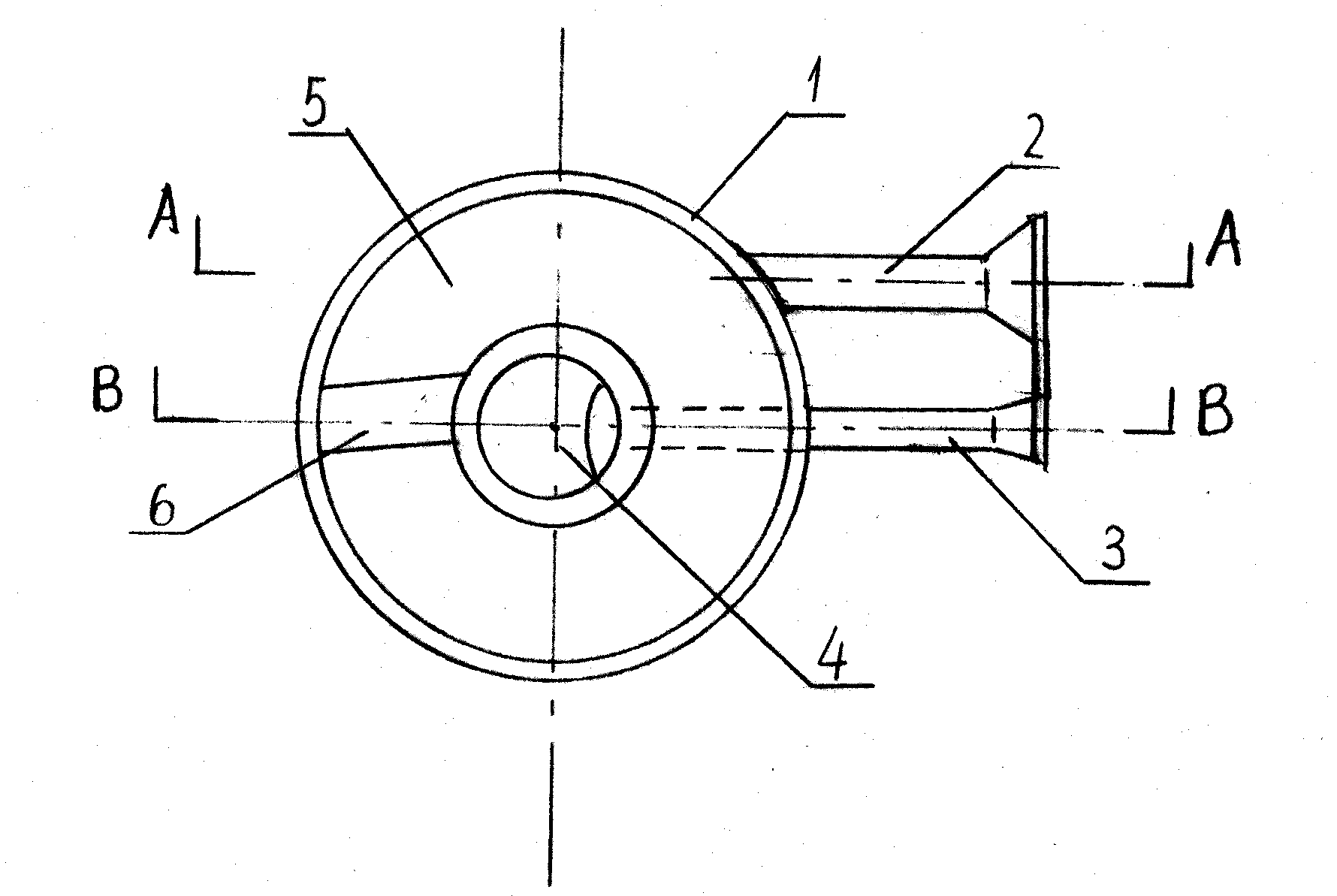
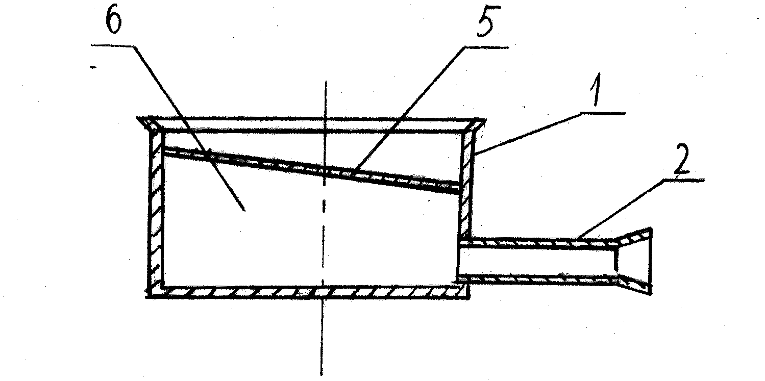
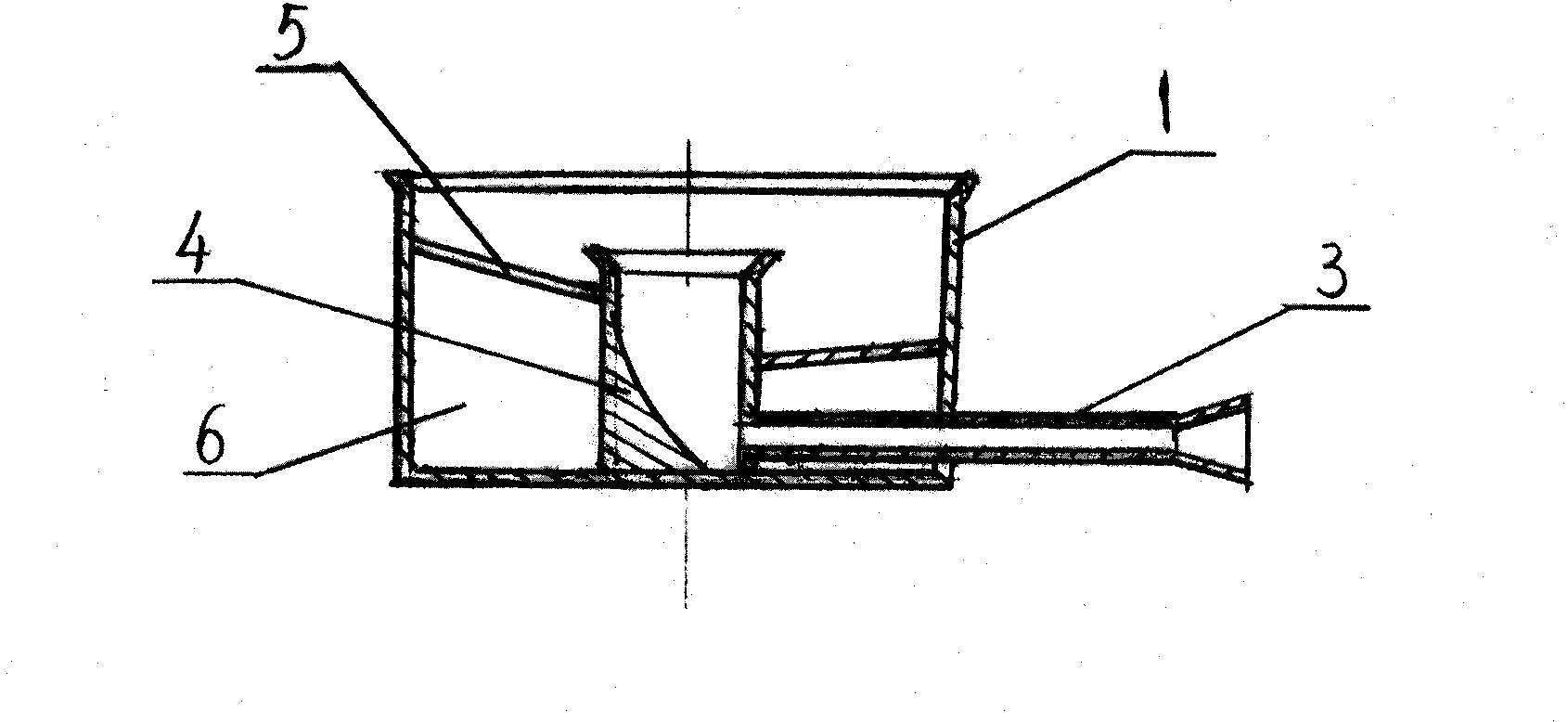
[0011] Embodiments of the present invention will be described in detail below in conjunction with the accompanying drawings. A gas mixer for a gas stove includes a barrel-shaped body 1, a bell-shaped central gas output barrel 4 is fixed on the central part of the barrel-shaped body 1, and a bell-shaped central gas output barrel 4 is fixed on the inner wall of the barrel-shaped body 1. An annular gas cavity 6 is formed between the outer walls of the central gas output barrel 4, and the inner gas delivery pipeline 3 and the outer gas delivery pipeline 2 fitted on the barrel-shaped body 1 are connected with the bell-shaped central gas delivery barrel 4 and the The annular gas cavity 6 is connected, and the axis line of the outer gas delivery pipeline 2 is arranged tangentially with the circumferential direction of the annular gas cavity 6, and the spiral gas guide vane 5 is arranged and installed in the annular gas cavity 6. The bottom end of the gas guide vane 5 contacts and coo...


PUM


Abstract

A combustion gas mixer used in a gas-cooker belongs to a gas stove appliance. Spiral rising combustion gas guide blades are arranged inside an annular combustion gas chamber. A bottom end of the spiral rising combustion gas guide blades contacts and is connectedly engaged with an inner wall surface at a bottom end of a barrel shape device body; a concave cambered projection is connectedly arranged between an inner wall surface and a sidewall internal surface at a bottom end of a bell mouth shaped center combustion gas output barrel, the concave cambered surface shaped projection faces a gas outlet of an inner combustion gas conveyer pipe. According to the invention, combustion gas is provided with assisting power for forced rapid rising in both the annular combustion gas chamber and the bell mouth shaped center combustion gas output barrel. The mixer of the invention has the advantages of strong flame, large combustion heat output, high temperature, full combustion gas combustion, rapid stove flame-up and flame-out responses, and good security.

Description

technical field [0001] The invention belongs to a gas stove, and mainly relates to a gas mixer used in a gas stove. Background technique [0002] The gas mixer is an important working part on the gas cooker. In order to improve the combustion efficiency of gas and the calorific value of the stove, a central gas output barrel is equipped in the barrel-shaped body, and an annular gas chamber is formed between the barrel-shaped body and the central gas output barrel, and the gas is delivered by two Gas mixers composed of pipelines have been applied to gas cookers. However, due to structural design flaws, after the gas enters the annular gas chamber, it only has a rotary power-assisted motion in the horizontal plane, and does not have the power-assisted motion of the gas rising rapidly. In addition, the gas entering the central gas output barrel has neither rotational power-assisted motion , and does not have the boost of rapid gas rise. The gas in the gas mixer can only rely ...

Claims


Application Information

Patent Timeline
Patent Type & Authority Applications(China)
IPC IPC(8): F23D14/62
Inventor 杜博韬
Owner 杜博韬
Why Eureka
Try Eureka