


Quick Research
Generate reliable direction feasibility study reports for your R&D in just a few steps.

Technical Q&A
Discover and master advanced knowledge NOW. Basics, ideas, possibilities, all at once.

Find Solutions
As an expert in R&D theories, this can generate solutions to your technical problems instantly.

Evaluate Feasibility
Analyze your overall solution with one click, know your potential R&D risks in advance.

Monitor Landscape
Get weekly tech updates, stay abreast of the latest tech innovations and key insights.
LED (light emitting diode) lamp
A technology of LED lamps and LED chips, applied in lighting devices, cooling/heating devices of lighting devices, light sources, etc., can solve the problems of short heat dissipation path, low luminous efficiency, short life, etc., and achieve high heat dissipation efficiency and good heat dissipation effect. , the effect of convenient processing
- Summary
- Abstract
- Description
- Claims
- Application Information
AI Technical Summary
Problems solved by technology
Method used
Image

Examples
Embodiment 1
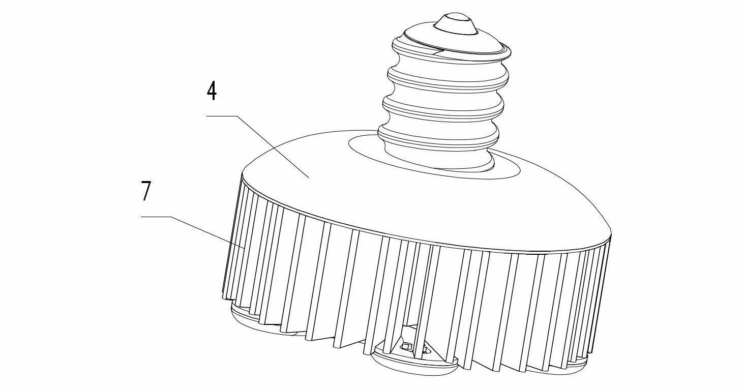
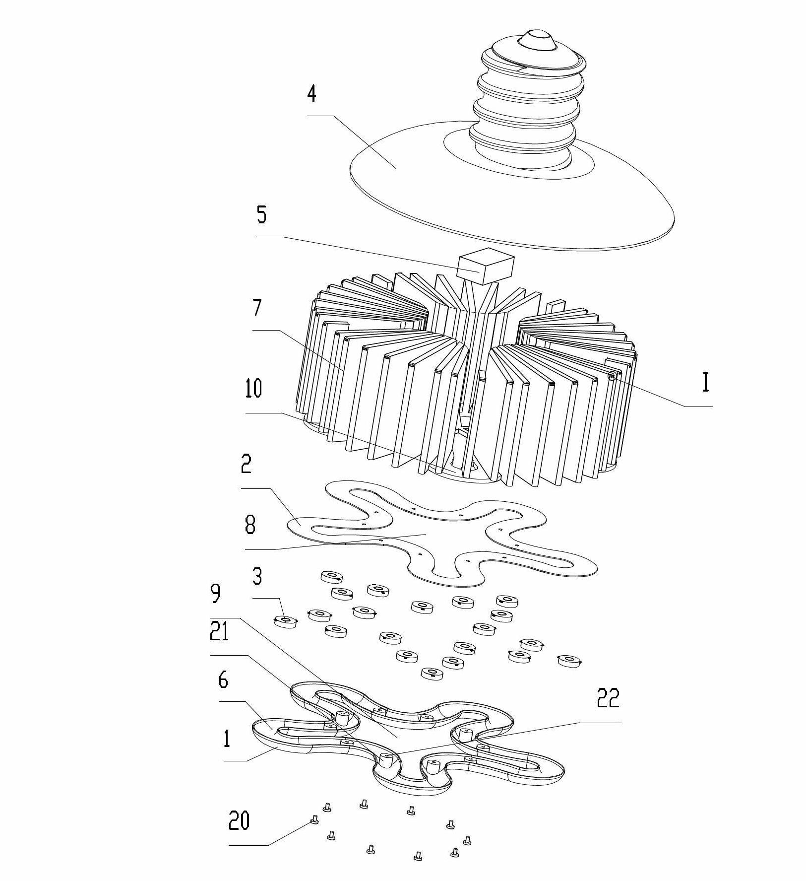
[0039] like Figure 1 to Figure 4 As shown, an LED lamp includes a light-transmitting lamp cover 1, a heat-dissipating PCB board 2, a heat-dissipating seat 10, a plurality of LED lamp beads 3 containing only one LED chip, a lamp holder 4, and positive and negative electrodes electrically connected to the LED lamp beads 3. The conductive layer of the layout circuit of the pins (not shown), the electric control device 5 electrically connected with the external power supply and the LED light emitting unit. The electric control device 5 is fixed on the lamp cap 4 . The LED lamp beads 3 are arranged in a similar pentagonal shape, fixed on the heat dissipation PCB board 2, the conductive layer of the layout circuit is directly arranged on the heat dissipation PCB board 2, and the LED lamp beads 3 and the conductive layer of the layout circuit are arranged on the same side of the heat dissipation PCB board 2 face.
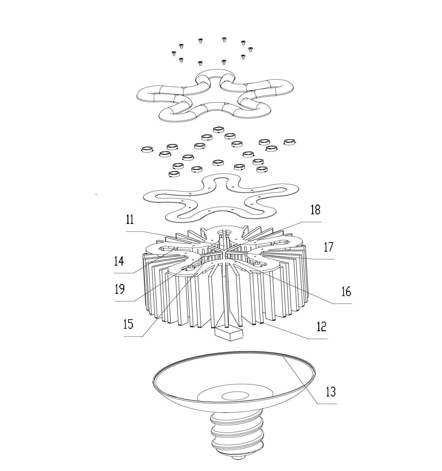
[0040]The outer peripheral shape of the heat sink 10, the heat dis...
Embodiment 2
[0043] like Figure 5 As shown, an LED lamp includes a light-transmitting lamp cover 30, a plastic plate 37 forming a lens, a PCB board 31, a heat dissipation base 32, an LED light-emitting unit, and a layout circuit conductive layer (not shown) electrically connected to the LED light-emitting unit. output), an electric control device 34 and a lamp holder 35 electrically connected to the external power supply and the conductive layer of the layout circuit. The LED lighting unit includes an LED chip 36 , a lens 45 , and a gold wire 33 electrically connecting the LED chip 36 and the conductive layer of the layout circuit.
[0044] The heat dissipation base 32 includes an annular flat bottom plate, and a plurality of chip fixing bosses 40 protruding from the bottom plate integrally formed with the heat dissipation base 32 , and the fixing bosses 40 are all distributed on the same circumference. A fixing column 39 is extended on the end surface of the plastic plate 61 forming the...
PUM
 Abstract
Description
Claims
Application Information
 - R&D Engineer
- R&D Manager
- IP Professional
- Industry Leading Data Capabilities
- Powerful AI technology
- Patent DNA Extraction
Browse by: Latest US Patents, China's latest patents, Technical Efficacy Thesaurus, Application Domain, Technology Topic, Popular Technical Reports.
© 2024 PatSnap. All rights reserved.Legal|Privacy policy|Modern Slavery Act Transparency Statement|Sitemap|About US| Contact US: help@patsnap.com