
Integral laser cutting head

A laser cutting head, laser cutting technology, applied in laser welding equipment, welding equipment, metal processing equipment, etc., to achieve the effect of convenient maintenance and replacement, and ensure the consistency of installation

Inactive Publication Date: 2012-09-26
上海致凯捷激光科技有限公司
View PDF10 Cites 9 Cited by
  • Summary
  • Abstract
  • Description
  • Claims
  • Application Information

AI Technical Summary

Problems solved by technology

[0002]The traditional laser cutting machine adopts a relatively loose optical path structure, and the laser and optical components are scattered and installed in the cutting machine frame. Thermal deformation occurs, which affects the reliability and stability of the laser optical path, and the protection of laser components is also difficult to achieve. In laser equipment, it is very important to prevent dust and moisture of optical devices, because the damage of optical devices is mainly due to It is caused by the damage caused by the dust and water vapor adsorbed on the device after being irradiated by the laser.
In addition, the components in the scattered installation machine are prone to interference from other components and cause instability. Once the device is damaged, the replacement of the device needs to be operated by professionals, and the optical path calibration is very complicated, and the maintenance work takes a long time

Method used


Image

  • Integral laser cutting head
  • Integral laser cutting head
  • Integral laser cutting head

Examples


Embodiment Construction

[0032] The present invention will be further described below in conjunction with embodiment, but should not limit protection scope of the present invention with this.

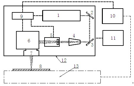
[0033] see first figure 1 , figure 2 , image 3 , Figure 4 , Figure 5 , Figure 6 , figure 1 It is a structural block diagram of the device of the present invention and a schematic diagram related to related devices, figure 2 It is a front view (excluding the front panel) of the box base frame 12 of the present invention, image 3 It is the right side view of the box base frame of the present invention, Figure 4 It is the rear view of the box base frame of the present invention (excluding the rear panel), Figure 5 It is the bottom view of the box pedestal of the present invention, Figure 6 It is the AA cross-sectional view of the box base frame of the present invention. It can be seen from the figure that the integrated laser cutting head for laser cutting of the present invention includes a ...


PUM


Abstract

The invention relates to an integral laser cutting head for laser processing of materials, comprising a laser, a first reflector, a second reflector, an extender lens, a dynamic focusing mechanism, a high-speed scanning vibrating mirror, an F-Theta field lens, a laser and scanning control system and a rectangular sealed box body, wherein the laser, the first reflector, the second reflector, the extender lens, the dynamic focusing mechanism, the high-speed scanning vibrating mirror, the F-Theta field lens and the laser and scanning control system are sealed in the box body. The integral laser cutting head has the characteristics of stable structure, constant temperature constant humidity and no dust, can guarantee an ideal working environment required by the operation of the laser, can work independently for small-range cutting operation and can be matched with an X-Y platform to carry out large-range cutting operation.

Description

technical field [0001] The invention relates to a laser cutting machine, in particular to an integrated laser cutting head for laser cutting technical background [0002] The traditional laser cutting machine adopts a relatively loose optical path structure. Lasers and optical components are scattered and installed in the cutting machine frame. The frame is easily affected by the external temperature and thermally deformed, which affects the reliability and stability of the laser optical path. Moreover, the protection of laser components is also difficult to achieve. In laser equipment, it is very important to prevent dust and moisture of optical devices, because the damage of optical devices is mainly caused by the dust and water vapor adsorbed on the device after being irradiated by laser light. caused by the damage. Moreover, the components in the scattered installation machine are prone to interference from other components and cause instability. Once the device is dam...

Claims


Application Information

Patent Timeline
Patent Type & Authority Applications(China)
IPC IPC(8): B23K26/38B23K26/42B23K26/70
Inventor 施伟田怀勇蔡志武金英杰
Owner 上海致凯捷激光科技有限公司
Learn More