
Light-emitting diode (LED) display screen and LED display device

An LED display and LED lamp bead technology, applied in identification devices, optics, instruments, etc., can solve the problems of unfavorable LED display module mass production, long processing cycle, harsh application environment, etc., to avoid collision damage, meet the Heat dissipation requirements, the effect of strengthening the heat dissipation effect

Active Publication Date: 2012-09-19
BEIJING GLUX CREATIVE TECH
View PDF9 Cites 18 Cited by
  • Summary
  • Abstract
  • Description
  • Claims
  • Application Information

AI Technical Summary

Problems solved by technology

[0006] 2. The harsh application environment makes the product itself windproof. On this basis, the appropriate effect of the audience cannot be affected by setting light bars at intervals. High production capacity requires LED to optimize the production efficiency in terms of structure.
[0007] 3. In the existing display structure, the light board of the display module is directly fixed on the metal backboard. Although the circuit behind the light board can be directly contacted with the metal backboard to facilitate the heat dissipation, but due to the If there are chip components protruding from the surface, holes must be made at the corresponding positions on the metal back plate, so that the light board can be fixed on the metal back plate. In this way, the processing cycle of a hole is long, and the process requires processing accuracy. High, not conducive to mass production of LED display modules

Method used


Image

  • Light-emitting diode (LED) display screen and LED display device
  • Light-emitting diode (LED) display screen and LED display device
  • Light-emitting diode (LED) display screen and LED display device

Examples


Embodiment Construction

[0045] In order to describe the technical content, structural features, achieved goals and effects of the present invention in detail, the following will be described in detail in conjunction with the embodiments and accompanying drawings.

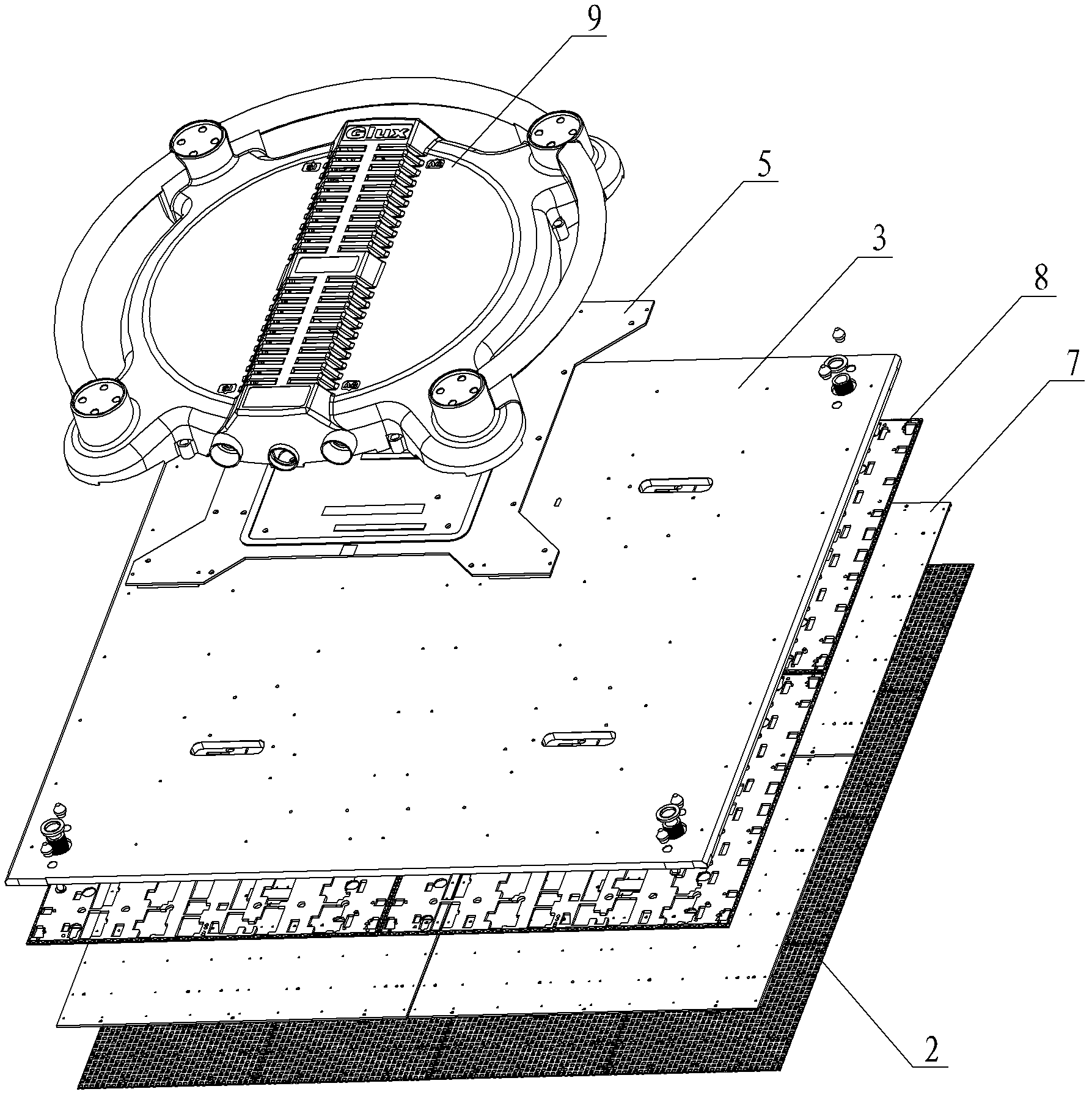
[0046] see figure 1 , The present invention relates to an LED display screen, which includes a mask 2, a lamp board 7, a thermal pad 8, a back board 3, a control board 5 and a housing 9. Wherein the mask 2 , the light board 7 , the heat conduction backing plate 8 , and the back plate 3 are sequentially stacked to form a display module, and the casing 9 covers the control board 5 and is fixed on the back plate 3 .

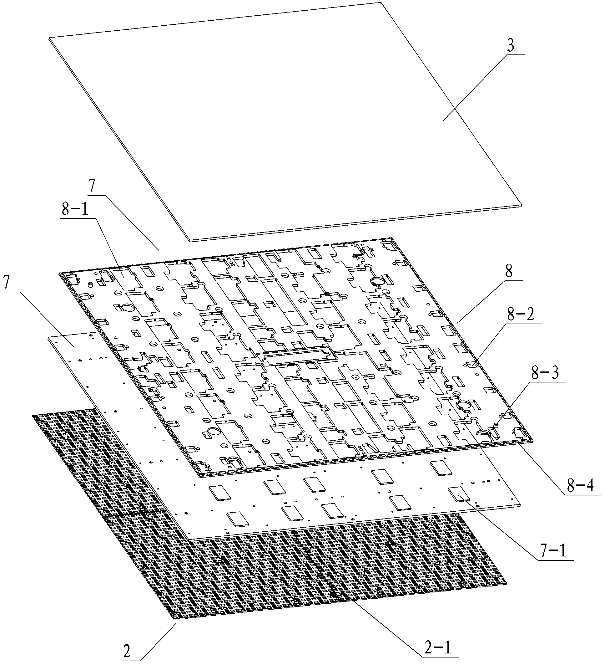
[0047] Such as figure 2 , LED display module sequentially stacked mask 2, lamp board 7, thermal pad 8 and back board 3.

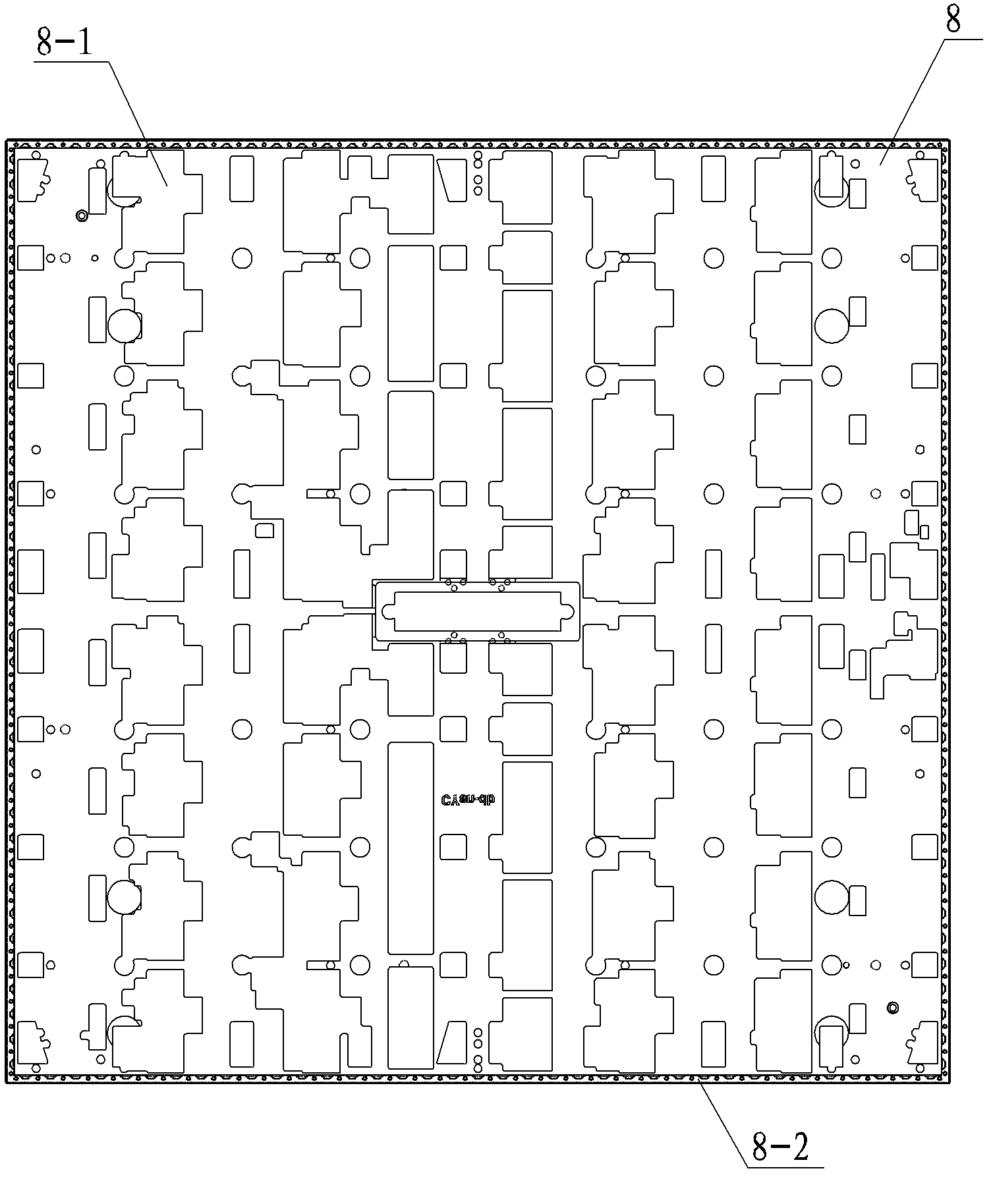
[0048] Wherein, the lamp board 7 is provided with LED lamp beads facing the side of the mask 2, and the corresponding mask 2 is provided with a through hole 2-1, and the mask 2 is covered outside the lamp ...


PUM


Abstract

The invention provides a light-emitting diode (LED) display screen and an LED display device and belongs to the technical field of LED display. The LED display screen comprises a mask, a lamp panel, a heat conduction base plate, a rear panel, a control panel and a casing, wherein the mask, the lamp panel, the heat conduction base plate and the rear panel are sequentially overlapped, and the casing is covered on the control panel and fixed on the rear panel. The LED display device is formed by connecting a plurality of the LED display screens by the aid of connecting pieces and connecting piece groups. According to the light-emitting diode (LED) display screen and the LED display device, a boss is arranged on the surface of the mask, so that LEDs on the lamp panel are well protected, less light is shielded, and visual angles of the LEDs are broadened; besides, the heat conduction base plate is added, so that even if a chip is protruded on the rear surface of the lamp panel, hole punching processing is not required to be performed to the rear panel, and the production efficiency of products is greatly increased; and a radiating hole and a radiating port are arranged on a rear casing, the whole casing is ventilated, accordingly, air circulation inside and outside the casing is facilitated, the radiating effect is enhanced, and the control panel is subjected to waterproof treatment in consideration of waterproof issues.

Description

technical field [0001] The invention relates to the field of LED display, in particular to an LED screen and an LED display device. Background technique [0002] In recent years, the application of large-area LED display devices composed of LED display screens has developed rapidly. LED display has become a symbol of urban information modernization. With the development of information digitization and display technology, it has been widely used in banks, airports, and stations. , stock exchange market, customs, stadium and stage and other places. [0003] However, the development of the existing LED display is encountering such as: the demand for large display area, the demand for harsh application environment and the demand for high production capacity, which undoubtedly constitutes a bottleneck for the further development of LED display. The main difficulties of the above requirements are as follows: [0004] 1. With the expansion of the LED display area, it is a big pro...

Claims


Application Information

Patent Timeline
Patent Type & Authority Applications(China)
IPC IPC(8): G09F9/33H05K7/20
CPCG02F1/113H05K7/20H05K7/20963
Inventor 兰侠谢光明白明黄金红徐小川田柯周付雄
Owner BEIJING GLUX CREATIVE TECH
Learn More