Circuit board module

A circuit board and module technology, which is applied in circuit layout, printed circuits connected with non-printed electrical components, lighting and heating equipment, etc. Monotony, single luminous effect and other problems, to achieve the effect of excellent visual effect, colorful and clear picture

Active Publication Date: 2013-12-04
江门市艺光科技开发有限公司
View PDF10 Cites 0 Cited by
  • Summary
  • Abstract
  • Description
  • Claims
  • Application Information

AI Technical Summary

Problems solved by technology

[0004] At present, the display boards or light boxes on the market use fluorescent tubes or LED lights to achieve illumination. These display boards or light boxes are all organic boards with patterns or characters, and the color effects are monotonous, lack of change, and the effect is single.
The luminous core of the display board or light box is the circuit board module and the panel that matches it, but the existing display board or light box can only have one kind of light in one area, and its luminous effect is single, and it cannot achieve multi-layer light or multi-layer light. The effect of luminous combination overlay

Method used


Image

  • Circuit board module
  • Circuit board module
  • Circuit board module

Examples


Embodiment 1

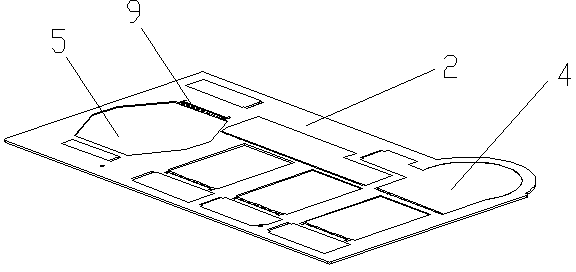
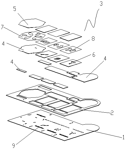
[0019] A circuit board module described in Embodiment 1 of the present invention, such as figure 1 , figure 2 As shown, it includes a circuit board 1 on which an LED light source 9 and positive and negative poles connected to the LED light source are provided on the circuit board. A positioning plate 2 that covers the circuit board and is not transparent to light is provided on the circuit board. The light guide plate assembly 3 corresponding to the position of the LED light source; the light guide plate assembly includes a plurality of first light guide plates 4 that allow the LED light source to be used as a background light source to realize light transmission and a plurality of second light guide plates 5 that allow the LED light source to be used as a work display light source to achieve light transmission . The first light guide plate is embedded in the positioning plate, and each first light guide plate corresponds to the position of the respective LED light source. ...

Embodiment 2

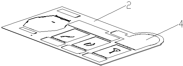
[0023] This embodiment 2 is changed on the basis of embodiment 1. Specifically, the positioning plate 2 and the first light guide plate 4 are combined into an integral structure, and each first light guide plate corresponds to the position of the respective LED light source, as shown in image 3 shown.


PUM


Abstract

The invention discloses a circuit board module which comprises a circuit board provided with an LED (Light Emitting Diode) light source and an anode and a cathode connected with the LED light source. The circuit board is provided with a lightproof positioning plate which covers the circuit board. The positioning plate is provided with a light guide plate assembly corresponding to the LED light source in position. The light guide plate assembly comprises at least a light guide plate such that the LED light source is taken as a background light source for transparency or / and the LED light source is taken as a work exhibition light source for transparency. By the arrangement of the light guide plate assembly, the whole light guide plate assembly forms a uniform light emitting surface when the LED light source emits light. For an independent light emitting area, a single-layer light guide plate assembly can be directly used as the background light source to emit light. For crossed and superposed light emitting areas or the light emitting areas in complex relationships, two or more layers of light guide plates are combined and superposed to form the light source to emit light and change to various suitable light emitting shapes and effects so as to achieve the optimal light emitting effect.

Description

technical field [0001] The invention relates to a circuit board module, in particular to a circuit board module specially used for LED flashing light boxes. Background technique [0002] Circuit boards are mainly used in the connection parts of electronic products, which have many advantages such as saving space, reducing weight and high flexibility, and are widely used in portable devices (such as mobile phones, notebook computers, etc.). The circuit board is mainly composed of the circuit board substrate and the conductive copper foil attached to it. [0003] Because LED has the advantages of small size, low power consumption, long service life, etc., LED is more and more widely used in people's daily life. Therefore, the design of the LED circuit board is particularly important. [0004] At present, the display boards or light boxes on the market all use fluorescent tubes or LED lights to achieve illumination. These display boards or light boxes are all organic boards w...

Claims


Application Information

Patent Timeline
Patent Type & Authority Patents(China)
IPC IPC(8): F21V23/00F21V8/00F21V7/22F21V13/02H05K1/18F21Y101/02F21Y115/10
Inventor 张开振
Owner 江门市艺光科技开发有限公司
Why Eureka
Try Eureka