Positioning locking mechanism for workpiece U-shaped groove

A positioning locking, U-shaped groove technology, applied in positioning devices, metal processing mechanical parts, manufacturing tools, etc., can solve problems such as large product gaps, changes in products and positioning boards, and unsatisfactory pass rates, reducing The effect of non-conforming product generation, reducing energy consumption, improving accuracy and quality

Active Publication Date: 2012-09-19
鹰普机械(宜兴)有限公司
View PDF8 Cites 0 Cited by
  • Summary
  • Abstract
  • Description
  • Claims
  • Application Information

AI Technical Summary

Problems solved by technology

Due to the difference in the gap and force of the elastic taper pin itself, it is impossible to find the ideal design state when processing workpieces with U-shaped grooves. In addition, the difference in the operation error of each person results in a large gap between the processed products. Unsatisfactory rate
In addition, clamps can also be used to directly position the U-shaped grooves, but due to the limited casting precision of the blank, the gap between the product and the positioning clamps will change, which requires sorting and processing, which is still not ideal

Method used


Image

  • Positioning locking mechanism for workpiece U-shaped groove
  • Positioning locking mechanism for workpiece U-shaped groove

Examples


Embodiment Construction

[0014] The present invention will be further described below in conjunction with the accompanying drawings and embodiments.

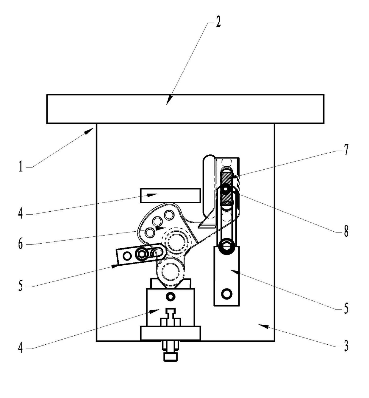
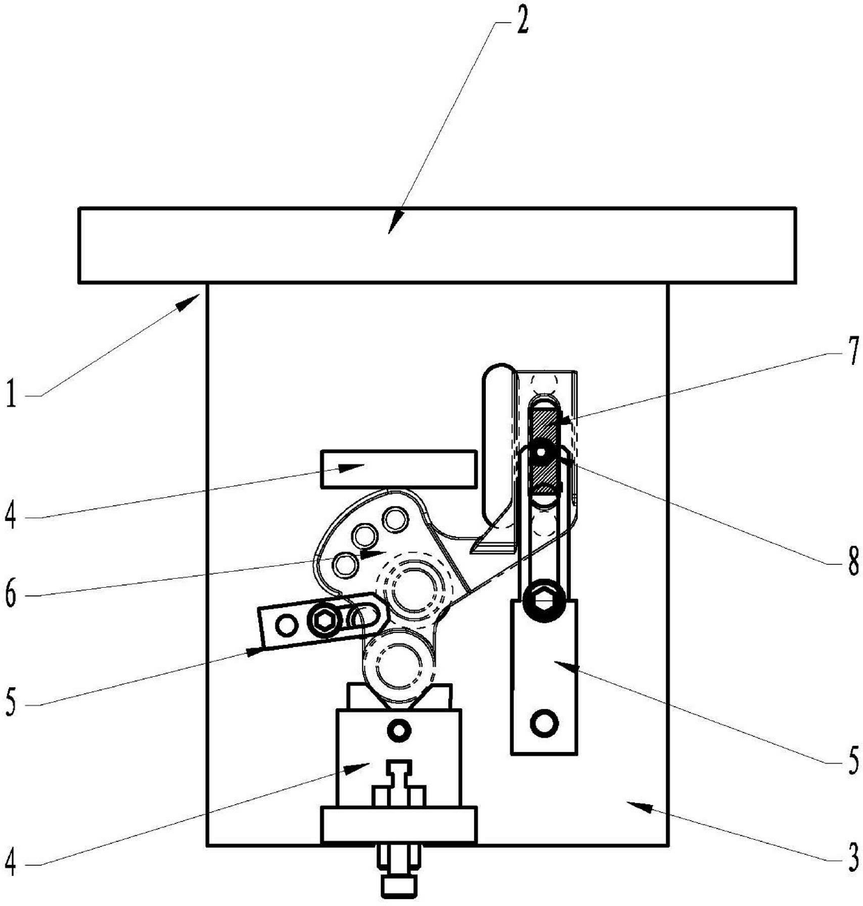
[0015] Such as figure 1 Shown: a positioning and locking mechanism for the U-shaped groove of the workpiece, including a tooling body 1, the tooling body 1 includes a bottom plate connector 2, a processing platform 3, an outer positioning structure 4 and a pressure plate 5, and the processing platform 3 is fixed on the bottom plate On the side wall of the connector 2, the outer positioning structure 4 and the pressing plate 5 are installed on the processing platform 3, the outer wall of the workpiece 6 is fixed on the processing platform 3 through the outer positioning structure 4 and the pressing plate 5, and the workpiece 6 is located under the pressing plate 5 side. In order to locate and lock the U-shaped groove of the workpiece, a fixed stopper 7 is provided on the processing platform 3. The stopper 7 is located at the position of the U-shaped gro...


PUM


Abstract

The invention discloses a positioning locking mechanism for a workpiece U-shaped groove. The positioning locking mechanism comprises a tooling body (1) comprising a base plate connection part (2), a processing platform (3), an external positioning structure (4) and a pressing plate (5). The processing platform (3) is fixedly arranged on the lateral wall of the base plate connection part (2), the external positioning structure (4) and the pressing plate (5) are installed on the processing platform (3), and the outer wall of a processing part (6) is fixed on the processing platform (3) through the external positioning structure (4) and the pressing plate (5). A limit block (7) is fixedly arranged on the processing platform (3) and located at the position of a U-shaped groove of the processing part (6), and a cam bolt (8) is arranged on the limit block (7). By means of the limit block and the cam bolt, product deflection is avoided, the number of unqualified produces is reduced, accuracy and quality of products are improved simultaneously, and energy consumption is reduced. Therefore, the positioning locking mechanism for the workpiece U-shaped groove is suitable for popularization and application.

Description

technical field [0001] The invention relates to the technical field of machining, in particular to a positioning and locking mechanism for a U-shaped groove of a workpiece. Background technique [0002] At present, there are many products processed symmetrically with U-shaped grooves. When processing many dimensions related to U-shaped grooves in workpieces with U-shaped grooves, the elastic taper pin is mainly used to position the U-shaped grooves, and the U-shaped grooves are pressurized. The board locks tightly. Due to the difference in the gap and force of the elastic taper pin itself, it is impossible to find the ideal design state when processing workpieces with U-shaped grooves. In addition, the difference in the operation error of each person results in a large gap between the processed products. The rate is not ideal. In addition, clamps can also be used to directly position the U-shaped grooves. However, due to the limited casting accuracy of the blank, the gap ...

Claims


Application Information

Patent Timeline
IPC IPC(8): B23Q3/06
Inventor 曹广利于委李明强董会科赵俊凯田荣祥
Owner 鹰普机械(宜兴)有限公司
Why Eureka
Try Eureka