Spring auxiliary support

A technology of auxiliary support and support shaft, applied in the field of spring supports, to achieve the effect of not easy to vibrate

Inactive Publication Date: 2012-09-19
鹰普机械(宜兴)有限公司
View PDF6 Cites 8 Cited by
  • Summary
  • Abstract
  • Description
  • Claims
  • Application Information

AI Technical Summary

Problems solved by technology

[0004] Purpose of the invention: The purpose of the present invention is to overcome the deficiencies in the prior art and provide a spring auxiliary support with stable force control, no vibration of parts during processing, and no vibration marks on the processing surface

Method used


Image

  • Spring auxiliary support
  • Spring auxiliary support
  • Spring auxiliary support

Examples


Embodiment Construction

[0017] The present invention will be further described below in conjunction with the accompanying drawings and embodiments.

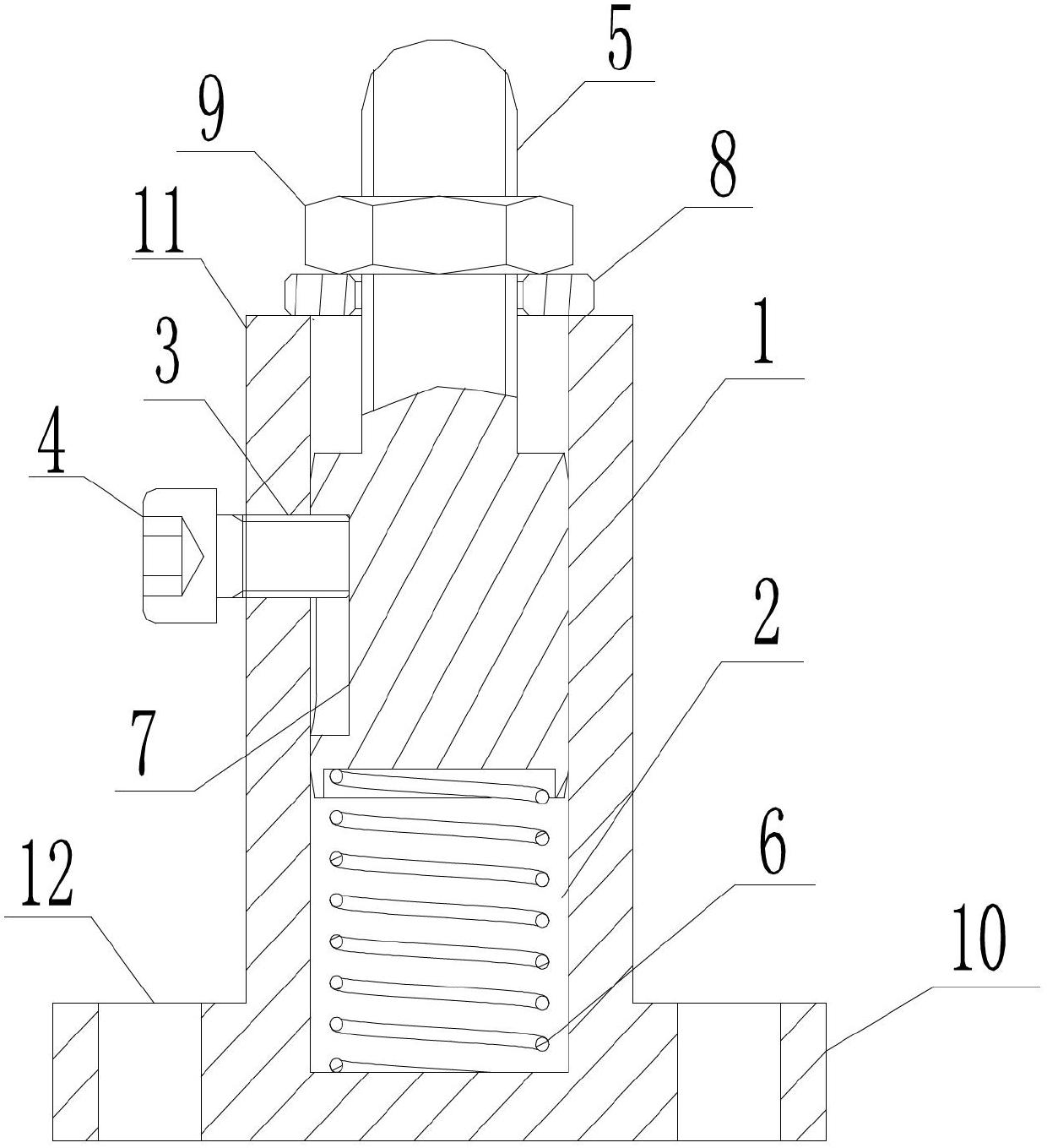
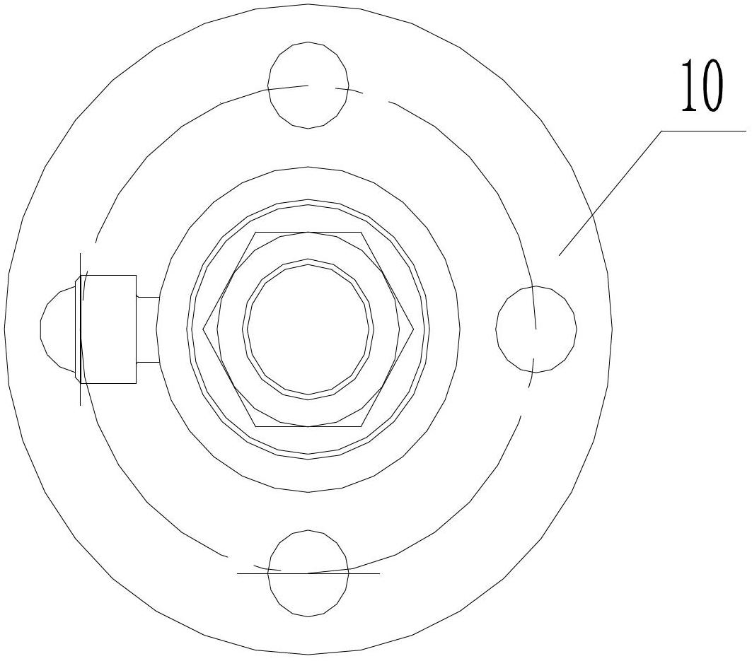
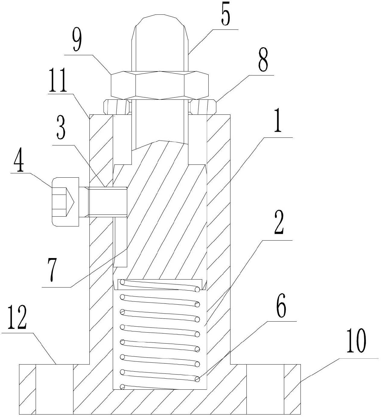
[0018] Such as figure 1 with figure 2 As shown, a spring auxiliary support according to the present invention includes a base 1, a shaft hole 2 is arranged in the middle of the base 1, a screw hole 3 is provided on the side of the base 1, and in the screw hole 3 A hexagon socket head screw 4 is provided, a support shaft 5 is movable in the shaft hole 2, a spring 6 is provided between the bottom of the shaft hole 2 and the support shaft 5, and a keyway 7 is provided on the side of the support shaft 5 , a flat pad 8 and a hexagonal thin nut 9 are arranged on the upper part of the support shaft 5; the base 1 includes a circular chassis 10 and a pillow block 11 with a shaft hole 2 in the middle of the circular chassis 10; the flat pad 8 and a hexagonal thin nut 9 are arranged outside the base 1; the upper part of the support shaft 5 is a threaded end; a ...


PUM


Abstract

The invention relates to a spring auxiliary support which comprises a base. A shaft hole is arranged in the middle of the base, a screw hole is arranged on the lateral face of the base, and an inner hexagon screw is arranged in the screw hole. A supporting shaft is movably arranged in the shaft hole, a spring is arranged between the bottom of the shaft hole and the supporting shaft, a key groove is arranged on the lateral face of the supporting shaft, and a flat gasket and a hexagon thin nut are arranged at the upper portion of the supporting shaft. The spring auxiliary support is stable in force control and does not easily generate vibration when parts are machined, and vibration lines on the machining surfaces are avoided.

Description

technical field [0001] The invention relates to a support component, in particular to a spring support piece. Background technique [0002] The support is a positioning element for the positioning of the machining plane, which acts as a support point and is used to limit a degree of freedom of the workpiece. Its purpose is to increase the contact point with the workpiece, reduce the deformation of the workpiece or reduce the contact stress. The height position of the auxiliary support is determined by the supported surface after positioning, without positioning, the determined position of the main positioning surface (bottom surface) of the part must not be damaged, and the thin-walled and overhanging parts on the part are supported to enhance the rigidity of these parts and reduce processing deformation during the process or to prevent vibration. [0003] The original support just utilizes common screw hand to tighten the jacking parts. If the jacking force is too large,...

Claims


Application Information

Patent Timeline
Patent Type & Authority Applications(China)
IPC IPC(8): B23Q3/00
Inventor 钱惠新陈翔许军峰程圣洋熊凡于吉强宋华肖太魁刘悦军
Owner 鹰普机械(宜兴)有限公司
Why Eureka
Try Eureka