
Reactor and method for producing particle materials

A particle material and reactor technology, applied in chemical instruments and methods, carbon preparation/purification, chemical/physical processes, etc., can solve problems such as affecting product collection, reducing product yield, reducing product yield, etc.

Active Publication Date: 2012-09-19
储晞
View PDF3 Cites 9 Cited by
  • Summary
  • Abstract
  • Description
  • Claims
  • Application Information

AI Technical Summary

Problems solved by technology

[0010] After the raw material gas is sent into the reactor cavity, it needs to pass through the set gas distributor, so that the raw material gas can react as fully as possible in the reaction chamber to improve the utilization rate of the raw material gas and the yield of the particle product. The cavity decomposes at any time, causing the air inlet and the air inlet of the gas distributor to be blocked due to particle deposition, which needs to be cleaned regularly, which not only reduces the product yield, but also makes it difficult to meet the needs of continuous production;
[0011] The raw material gas decomposes to form simple substance deposition, which makes the particle seeds grow up, and also causes the particles to easily bond and form agglomeration in the cavity, which affects the collection of products, and can only interrupt production for necessary treatment;
[0012] The elemental substances decomposed by the raw material gas in the reactor cavity are not only deposited on the surface of the particle seeds, but also deposited on the inner wall of the cavity, which reduces the product yield. The reactor cavity deposited on the inner wall needs to be replaced frequently, which seriously affects the reaction. continuity

Method used


Image

  • Reactor and method for producing particle materials
  • Reactor and method for producing particle materials
  • Reactor and method for producing particle materials

Examples


Embodiment 1

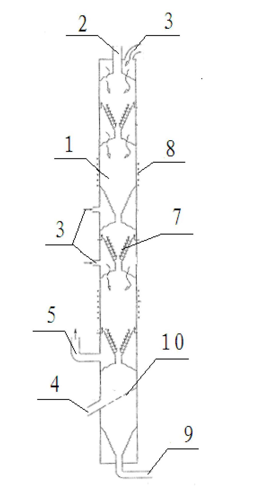
[0092] Figure 1a The schematic diagram of the reactor for producing granular materials provided in the first embodiment; Figure 1b for Figure 1a Schematic diagram of the structure of the mid-cone distributor; figure 2 Schematic diagram of the structure of the particle transport mechanism; Figure 3a , Figure 3b Is a schematic diagram of the structure of the reactor cavity gas curtain; Figure 3c , Figure 3d It is a schematic diagram of the structure of the gas curtain of the raw gas inlet pipe.

[0093] The reactor for producing particulate material provided in this implementation is used to generate particulate material (silicon) from the pyrolysis of raw material gas (silane).

[0094] Such as Figure 1a The reactor shown for producing granular materials includes: a reactor cavity 1;

[0095] The reactor cavity 1 is provided with at least a particle feeding hopper 2, a raw material gas inlet 3, a particle product discharge port 4, and a tail gas outlet 5. Among them, the reactor ...

Embodiment 2

[0129] This embodiment discloses a method for producing granular materials by using a reactor for producing granular materials to thermally decompose nickel carbonyl to prepare nickel granular materials, including the following steps:

[0130] a. Add the nickel granular material seeds into the reactor cavity through the particle feeding hopper, so that the nickel granular material seeds form a stacked particle bed in the reaction zone, and the filling rate of the nickel granular material seeds in the stacked particle bed is above 60%; The filling rate is the volume of the nickel granular material seeds occupying the reaction zone.

[0131] b. Use the variable diameter reactor cavity and change the speed of replenishing the nickel granular material seeds to control the residence time of the nickel granular material seeds in the reactor cavity, and make the nickel granular material seeds in the stacked granular bed in a relative motion state ;

[0132] Heating the stacked particle bed...

Embodiment 3

[0137] Figure 4 The schematic diagram of the reactor for producing high-purity silicon granular material provided in Example 3.

[0138] by Figure 4 It can be seen that the reactor for producing high-purity silicon granular materials provided in this embodiment is an internally-moving close-packed bed reactor, which can be used for other related reactions such as pyrolysis of silane to generate granular high-purity silicon.

[0139] As shown in the figure, the reactor includes a reactor cavity. The bottom of the reactor cavity is an inverted cone. An auxiliary gas inlet 414 is provided at the lower end of the inverted cone. The auxiliary gas inlet 414 can be used to transport auxiliary gas (hydrogen); The side wall in the middle of the cavity is provided with a shutter distributor and a tail gas outlet 416; the top of the reactor cavity is provided with a seed feeding port 401 and a raw material gas inlet 415; the upper end of the reactor cavity side wall distributor is provided...


PUM


Abstract

The invention discloses a reactor and a method for producing particle materials. The reactor comprises a reactor cavity which is at least provided with a particle feeding hopper, a raw gas inlet, a particle product discharging port and a tail gas outlet, wherein the reactor cavity is internally provided with at least one conical distributor; the position of the tail gas outlet is higher than that of the conical distributor; the particle feeding hopper is arranged at the upper part of the reactor cavity; the particle product discharging port is arranged at the lower part of the reactor cavity; the reactor cavity also comprises an air curtain mechanism which can realize the blocking action between the reaction material and the inner wall of the reactor cavity; the reactor cavity is also provided with an internal or external mechanism for heating a reaction area; and the reactor cavity is also provided with an internal or external dynamic generation mechanism. The invention also discloses the method for producing the particle materials. According to the invention, the defects in the prior art are overcome, and the high-efficiency, energy-saving, long-term stable, safe and reliable production of the particle materials is realized.

Description

Technical field [0001] The present invention relates to granular material production technology, in particular to a reactor and method for producing granular material. Background technique [0002] In modern industrial production processes, the demand for particulate materials such as silicon, nickel, and titanium; silicon nitride, silicon carbide, and silicon oxide compounds are increasing in demand, and their performance requirements are becoming more and more demanding: The granular material should meet higher purity requirements; and the granularity should be uniform and moderate; the production cost of the granular material should not be too high to meet the needs of large-scale continuous production. [0003] At present, the preferred reactor for the production of granular materials is a fluidized bed reactor, which uses selected raw material gases (which can be decomposed at high temperatures, or undergo reactions such as reduction, oxidation, nitridation, and the chemical c...

Claims


Application Information

Patent Timeline
IPC IPC(8): B01J8/08C01B33/03C01B32/05
Inventor 储晞
Owner 储晞
Learn More