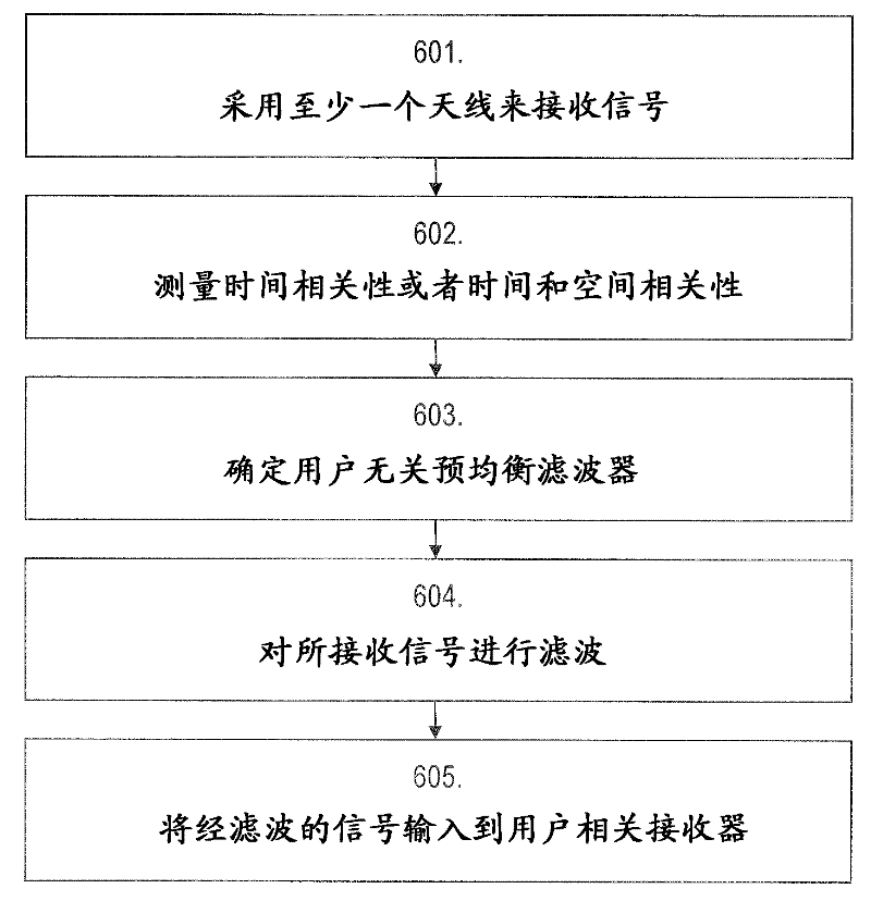
Spatial and temporal pre-equalization
A pre-equalization and timing technology, applied in the field of WCDMA communication systems, can solve problems such as far from optimal receivers
- Summary
- Abstract
- Description
- Claims
- Application Information
AI Technical Summary
Problems solved by technology
Method used
Image

Examples
no. 1 example
[0068] In the first embodiment of the present invention, both temporal pre-equalization and spatial pre-equalization can be performed in a single stage (7, 8), as shown in FIG. 3 . For the frequency index , the frequency-domain samples received from all antennas (1A, 1B) are represented by
[0069] , which is based on the time interval (or block) of received samples. This block passes to enumerate. Frequency-domain spatial and temporal pre-equalization (8) as with The element-wise multiplication of . we got
[0070]
[0071] in
[0072]
[0073] and among them is the frequency-domain representation of a scalar spectral shaping filter (SSF), such as a raised cosine filter. it's here, is the result of the Cholesky factorization of the multi-antenna periodogram, namely
[0074]
no. 2 example
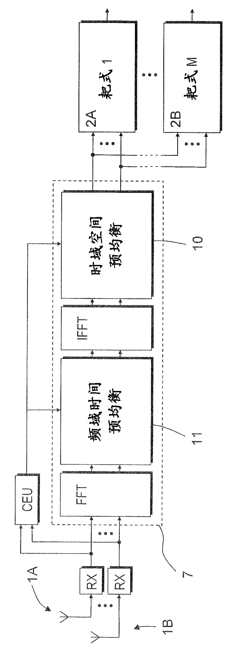
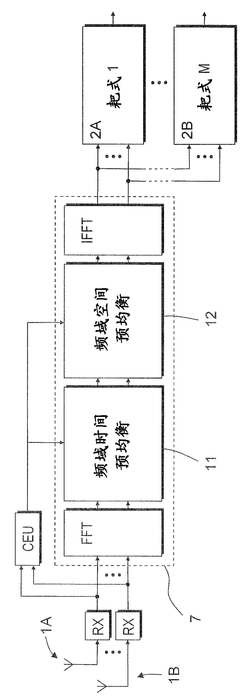
[0076] In the second embodiment of the present invention, MMSE pre-equalization can be divided into two stages: first temporal pre-equalization (9, 11), and then spatial decorrelation (10, 12). See Figures 4a and 4b for two alternative embodiments of this spatial and temporal pre-equalization.
[0077] In the first stage, for the number of antennas α, temporal pre-equalization (11) employs frequency-domain filter coefficients
[0078]
[0079] carry out, where is a scalar spectral shaping filter (SSF), such as a raised cosine filter, and is the frequency and block number A single-antenna periodogram. Notice, is real-valued and positive, which simplifies square root and division calculations.
[0080] For the number of antennas α, the periodogram can be estimated as a moving average
[0081]
[0082] in, is the appropriate scaling factor, e.g. . Alternatively, estimate the periodogram recursively,
[0083]
[0084] in, is an appropriate forgetting f...
no. 3 example
[0102] In a third embodiment of the invention, the frequency domain spatial decorrelation as described in the second stage of the previous subsection is performed in the time domain (10). For an illustration of this spatial and temporal pre-equalization, see Figure 5 .
[0103] At the first level, temporal pre-equalization (11) is performed as in the previous node, i.e. as an element-wise scalar multiplication
[0104]
[0105] For each antenna α, frequency index and blocks ,in
[0106]
[0107] The time-domain form of the time-pre-equalized signal of antenna α is expressed as
[0108]
[0109] By using an "overlap and add" approach such as Figure 7 As shown, a new time domain sequence is constructed. This is determined by each antenna α is represented by and the runtime index is continuous sequence of . In vector representation, time The temporally pre-equalized signal is expressed as
[0110]
[0111] In the second stage, time domain spatial decor...
PUM
 Abstract
Description
Claims
Application Information
 - R&D
- Intellectual Property
- Life Sciences
- Materials
- Tech Scout
- Unparalleled Data Quality
- Higher Quality Content
- 60% Fewer Hallucinations
Browse by: Latest US Patents, China's latest patents, Technical Efficacy Thesaurus, Application Domain, Technology Topic, Popular Technical Reports.
© 2025 PatSnap. All rights reserved.Legal|Privacy policy|Modern Slavery Act Transparency Statement|Sitemap|About US| Contact US: help@patsnap.com