
Gas flow control device

一种气流控制装置、控制腔的技术,应用在阀装置、控制阀、功能阀类型等方向,能够解决限制使用场所、不便顺畅打开控制装置回气气路等问题

Active Publication Date: 2013-06-19
JIANGSU HAINA AIR CONDITIONER PURIFICATION EQUIP
View PDF4 Cites 0 Cited by
  • Summary
  • Abstract
  • Description
  • Claims
  • Application Information

AI Technical Summary

Problems solved by technology

[0002]Existing airflow control devices, especially piston-type airflow control devices, generate negative pressure in the piston cavity to attract the piston when returning air, which is not easy to open and control smoothly The return air path of the device
If one side of the piston chamber is communicated with the atmosphere, although the above-mentioned technical problems can be solved, the place of use will be limited because of the air leakage of the control device.

Method used


Image

  • Gas flow control device
  • Gas flow control device
  • Gas flow control device

Examples


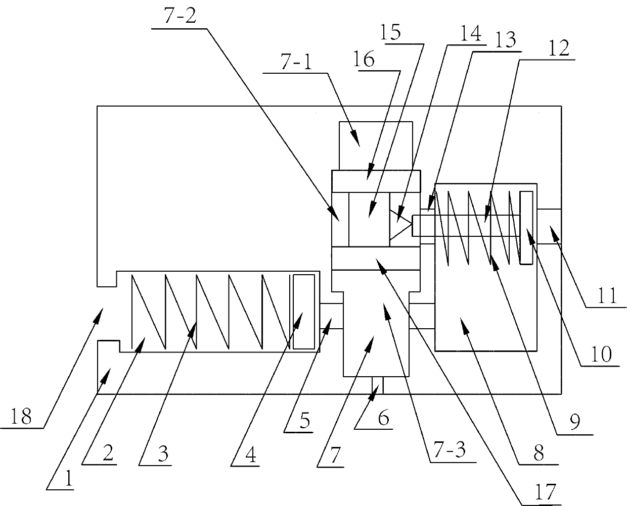
Embodiment 1

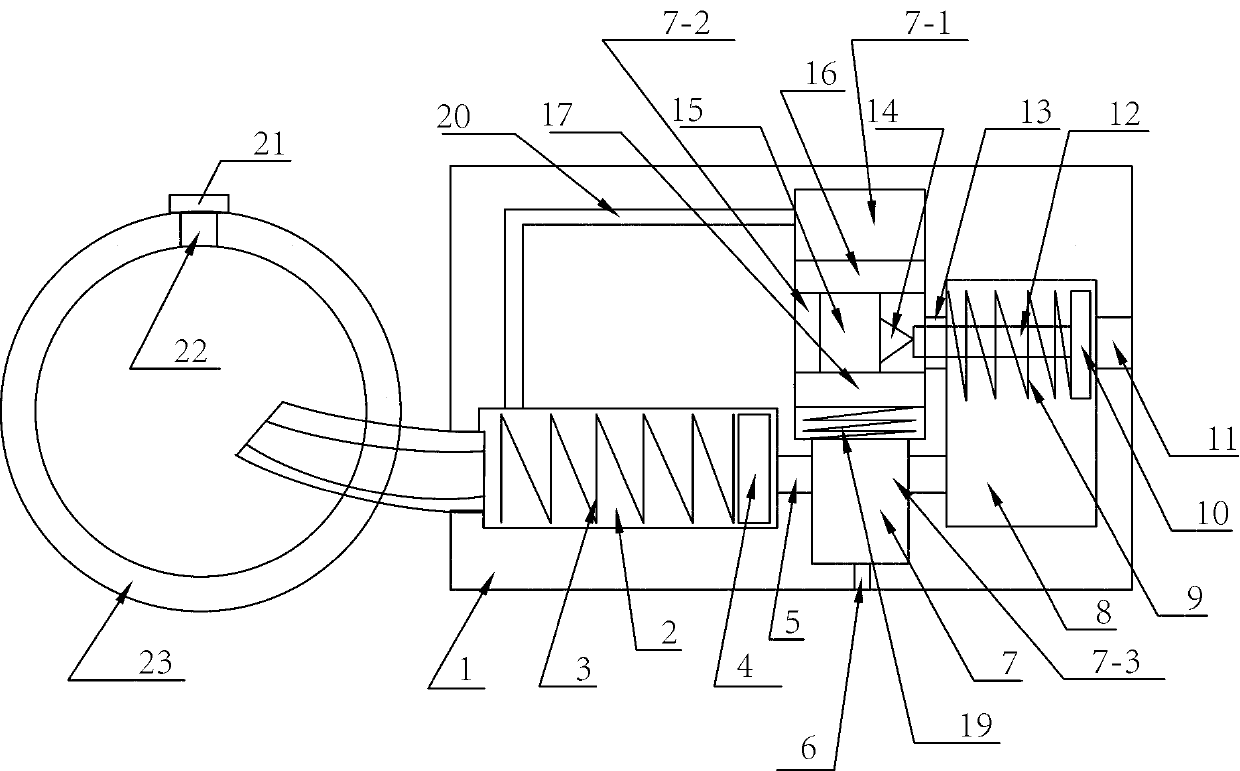
[0021] like figure 2 , on the basis of Embodiment 1, this embodiment also includes an auxiliary air bag 23 with an air filling hole 22, and an inflation check valve 21 is installed in the air filling hole 22, and the auxiliary air bag 23 is connected to the air filling hole. 18 in communication; it also includes a control air passage 20 opened in the body 1, one end of the control air passage 20 communicates with the first cavity 7-1, and the other end communicates with the inflation control chamber 2; it also includes a control air passage installed in the second The return elastic body 19 between the sealing head 17 and the cavity wall of the third cavity 7-3. The auxiliary air bag 23 is placed in the air container. The auxiliary airbag 22 is used to inflate an air container (such as an airbag, balloon, pipeline, etc.).

[0022] When inflating the gas container, the gas in the third cavity 7-3 presses against the second head 17, so that the connecting rod 15 moves axially...

Embodiment 2

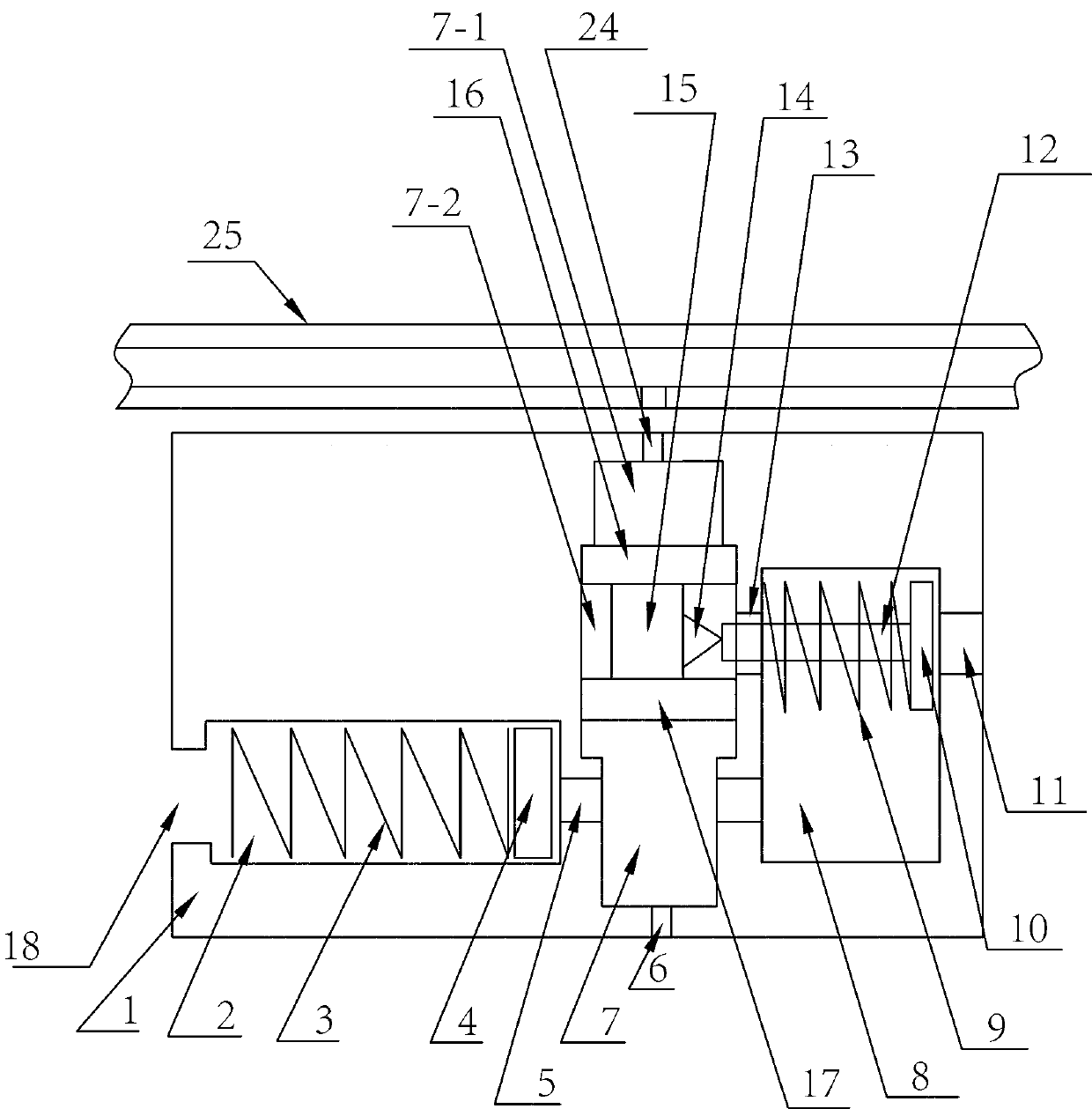
[0025] When the gas container is deflated, first press the first head 16 by controlling the air pipe 25, so that the outer end of the lock block 14 and the end head rod 12 of the deflation end are separated from extrusion, so as to open the vent hole 11 more smoothly. Then the gas container is deflated by the inflation and deflation control device 3 . During use, control air pipe 25 as normal pressure or high pressure gas as required.

[0026] Embodiment Four

Embodiment 3

[0028] The elastic body mentioned in the present invention includes springs, elastic sheets and the like.

[0029] The main body 1 is provided with an inflatable and exhaust port 6 communicating with the inflatable and exhaust cavity 7, and the inflated and exhaust port 6 communicates with the inflatable and deflated pipe during use. The vent hole 11 of the present invention is used to be connected with the gas container, and when the gas needs to be returned from the gas container to the inflation and discharge pipe, the gas in the gas container enters the airflow control device of the present invention through the vent hole 11, and finally Return to the inflation and deflation pipe through the inflation and exhaust port 6. The elastic body of the present invention includes springs and elastic sheets.


PUM


Abstract

The invention discloses a gas flow control device. A control gas passage is arranged in a body of the gas flow control device, one end of the control gas passage is connected with a cavity in the body, the other end of the control gas passage is connected with a cavity at a gland end of a connecting rod, and the gas flow control device is additionally provided with an auxiliary gas sac. When the gas flow control device is used for inflating, gas flow blocks a gas return passage, an inflating gas passage is opened, and one-way inflation is realized; when gas returns, the gas flow blocks the inflating gas passage, and the gas return passage is smoothly opened under the effect of the auxiliary gas sac; and when either inflation or gas return is not required, the gas flow control device can realize a pressure maintaining function.

Description

technical field [0001] The invention relates to an airflow control device used as a filling and deflation valve assembly. Background technique [0002] Existing airflow control devices, especially piston-type airflow control devices, generate negative pressure on one side of the piston cavity to attract the piston when returning air, which is not convenient for smoothly opening the return air path of the control device. If one side of the piston chamber is communicated with the atmosphere, although the above-mentioned technical problems can be solved, the place of use will be limited because of the air leakage of the control device. Contents of the invention [0003] The technical problem to be solved by the present invention is to provide an air flow control device that realizes one-way inflation and one-way return air, and can open the return air path of the control device more smoothly when returning air, so as to overcome the disadvantages of existing air valves. de...

Claims


Application Information

Patent Timeline
Patent Type & Authority Patents(China)
IPC IPC(8): F16K15/20
Inventor 吉昌辉
Owner JIANGSU HAINA AIR CONDITIONER PURIFICATION EQUIP
Learn More