
Shield machine synchronous grouting pipeline system and shield machine with same

A technology of synchronous grouting and pipeline system, applied in wellbore lining, tunnel lining, underground chamber, etc., can solve the problems of insufficient flushing, blockage of synchronous grouting pipeline system, inconvenient cleaning, etc., so as to shorten the maintenance time. , the effect of improving construction efficiency

Active Publication Date: 2012-09-12
WUHAN MARINE MACHINERY PLANT
View PDF8 Cites 15 Cited by
  • Summary
  • Abstract
  • Description
  • Claims
  • Application Information

AI Technical Summary

Problems solved by technology

[0005] Due to the long grouting pipe of the synchronous grouting pipeline system, a large amount of residue will accumulate and adhere for a long time, and the grouting pipe of the synchronous grouting pipeline system is buried in the shield tail structure and cannot be disassembled, so cleaning is very inconvenient and If the flushing is not thorough enough, it is easy to cause blockage of the synchronous grouting pipeline system
In addition, if the synchronous grouting pipeline system is damaged, it is inconvenient to replace because the grouting pipe is buried in the shield tail structure and cannot be disassembled

Method used


Image

  • Shield machine synchronous grouting pipeline system and shield machine with same
  • Shield machine synchronous grouting pipeline system and shield machine with same
  • Shield machine synchronous grouting pipeline system and shield machine with same

Examples


Embodiment 1

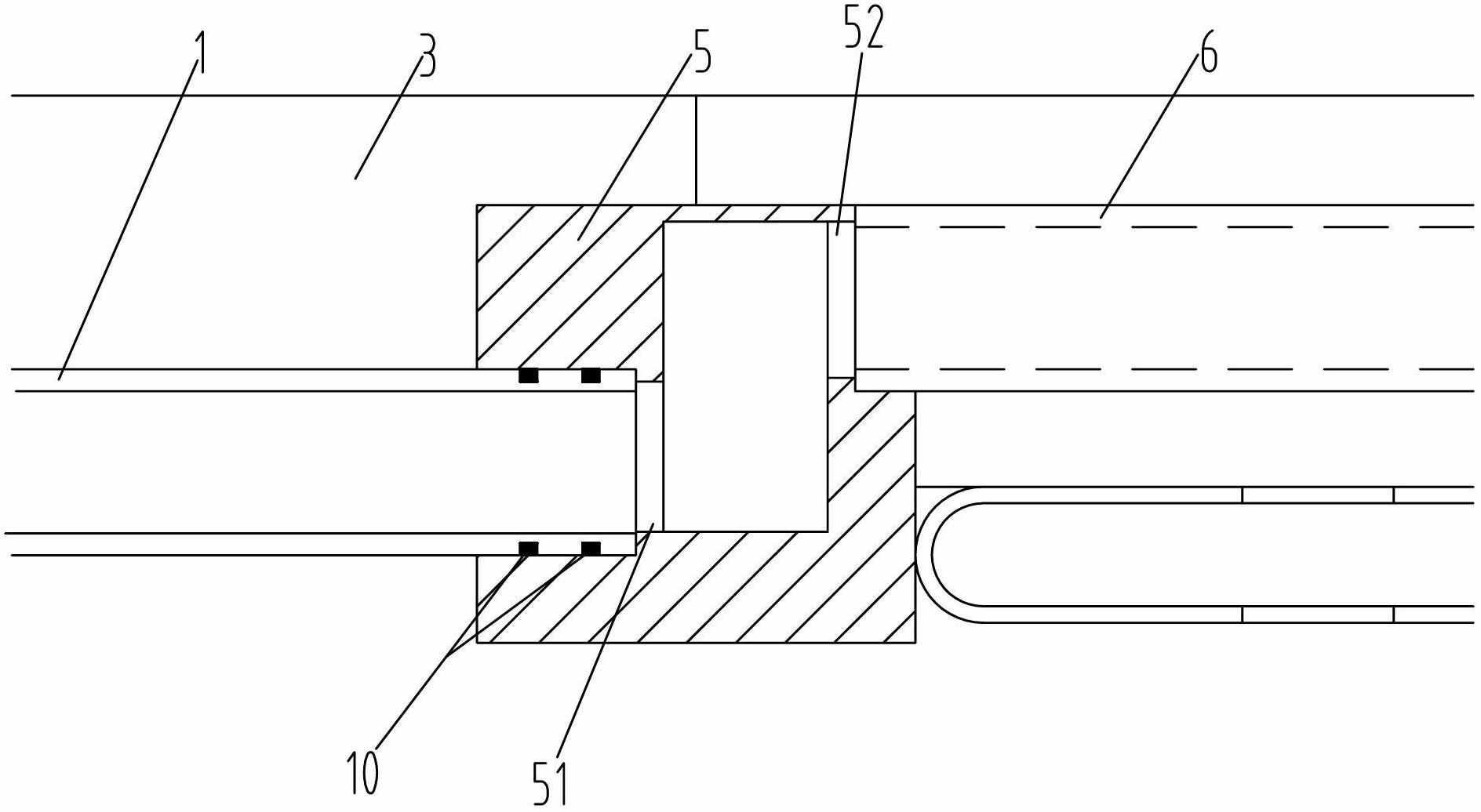
[0025] see figure 1 and figure 2 , the embodiment of the present invention provides a shield machine synchronous grouting pipeline system, the system includes: several grouting pipelines, each grouting pipeline includes a first grouting pipe 1, and a first grouting pipe A gate valve 2 detachably connected to one end of 1, a fixed structure 4 for detachably installing the first grouting pipe 1 on the inner wall of the shield tail 3, a transition block 5 arranged on the inner wall of the shield tail 4, and the second grouting The two ends of the pipe 6 and the transition block 5 are respectively provided with a first connecting hole 51 and a second connecting hole 52, the first connecting hole 51 and the second connecting hole 52 communicate with each other, the other end of the first grouting pipe 1 is connected to the first The connecting hole 51 is detachably connected, and one end of the second grouting pipe 6 is connected to the second connecting hole 52 , and the second ...

Embodiment 2

[0038]An embodiment of the present invention provides a shield machine, including a shield machine body and a synchronous grouting pipeline system installed in Embodiment 1 of the shield machine body.


PUM


Abstract

The invention discloses a shield machine synchronous grouting pipeline system and a shield machine with the same, belonging to the technical field of tunnel engineering. The system comprises multiple grouting pipelines; each grouting pipeline comprises a first grouting pipe, a gate valve, a fixing structure, a transition block and a second grouting pipe; the gate valve is detachably connected with one end of the first grouting pipe; the first grouting pipe is detachably mounted on the inner wall of the shield tail through the fixing structure; the transition block is arranged on the inner wall of the shield tail; a first connection hole and a second connection hole are arranged at the two ends of the transition block respectively and communicated with each other; the other end of the first grouting pipe is detachably connected with the first connection hole; one end of the second grouting pipe is connected with the second connection hole; and the other end of the second grouting pipe is communicated with a gap at the shield tail. According to the invention, since the first grouting pipe is detachably mounted on the inner wall of the shield tail through the fixing structure, the first grouting pipe can be independently dismantled for cleaning or replacement, the maintenance time of the grouting pipeline system is shortened, and the construction efficiency is improved.

Description

technical field [0001] The invention relates to the technical field of tunnel engineering, in particular to a shield machine synchronous grouting pipeline system and a shield machine with the system. Background technique [0002] Shield tunnel boring machine, referred to as shield machine, is a special construction machine for tunnel boring, widely used in subway, railway, highway, municipal, hydropower and other tunnel projects. When the shield machine is used for tunnel excavation construction, because the excavation diameter of the cutter head of the shield machine is larger than the outer diameter of the segment, when the assembled segment ring comes out of the tail of the shield, a certain gap will be formed between the stratum and the segment. Building voids, if not filled in time, will cause ground subsidence and affect surrounding buildings. Therefore, the shield machine is usually equipped with a synchronous grouting pipeline system to inject grout into the gap syn...

Claims


Application Information

Patent Timeline
IPC IPC(8): E21D11/10E21D9/08
Inventor 陈云节杨阳赵雷刚刘发展陈离
Owner WUHAN MARINE MACHINERY PLANT
Learn More