
Central winding machine

A technology of winding machine and winding shaft, which is applied in the direction of winding strips, thin material processing, transportation and packaging, etc., and can solve the problems of low production efficiency and cumbersome operation

Active Publication Date: 2015-03-25
SHANTOU DACHENG ENVIRONMENTAL PROTECTION PRECISION MACHINE TECH CO LTD
View PDF8 Cites 0 Cited by
  • Summary
  • Abstract
  • Description
  • Claims
  • Application Information

AI Technical Summary

Problems solved by technology

Cutting and receiving materials manually, the operation is cumbersome and the production efficiency is low

Method used


Image

  • Central winding machine
  • Central winding machine
  • Central winding machine

Examples


Embodiment Construction

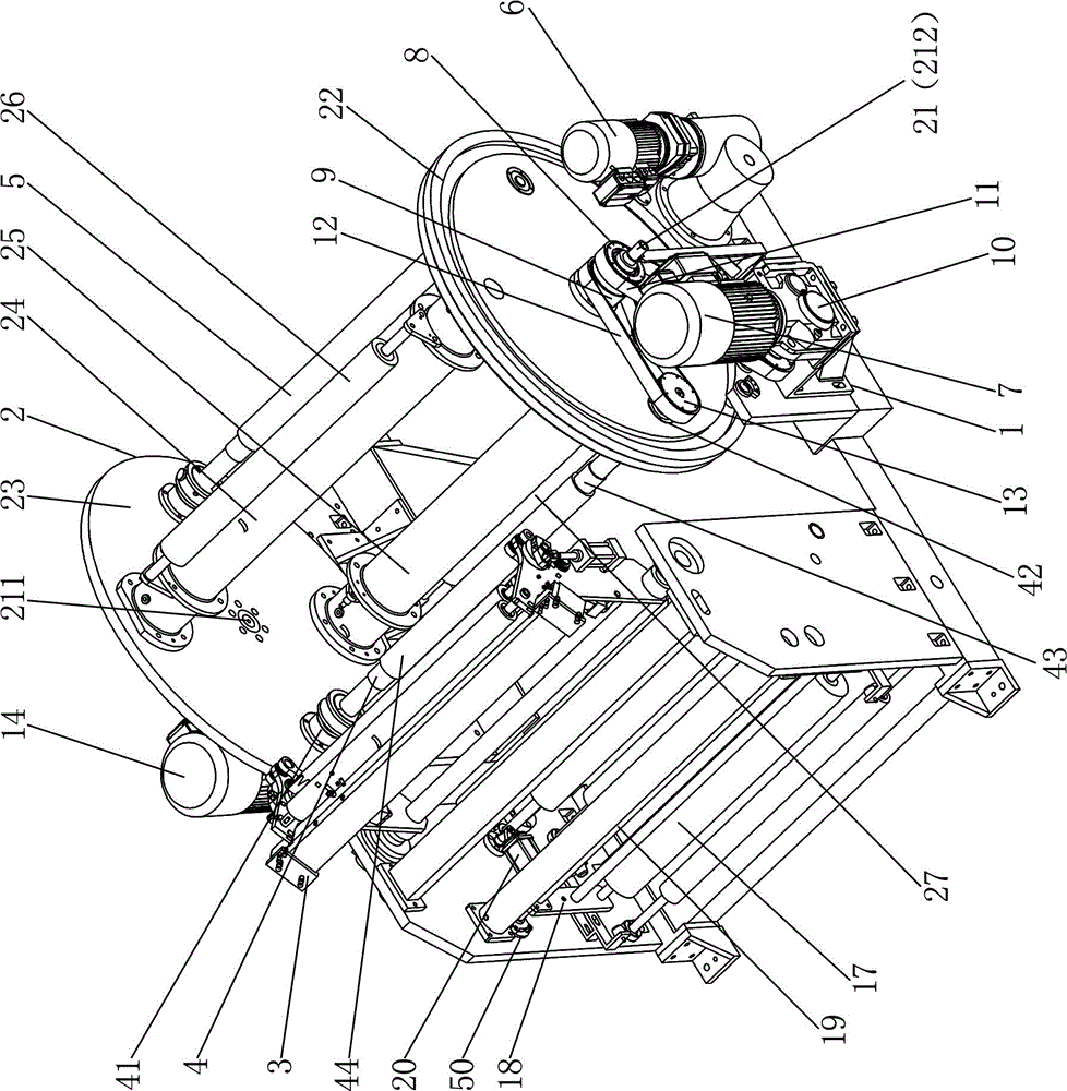
[0037] Such as figure 1 As shown, this central winder includes a frame 1, an overturn frame 2, a material receiving mechanism 3 and a winding tension mechanism.

[0038] In the present embodiment, the overturn frame comprises a support shaft 21, an overturn gear 22, a circular wall plate 23, a first support rod 24 and a second support bar 25, and the overturn gear 22 is parallel to the circular wall plate 23 (the overturn gear 22 and the circular wall plate 23 are parallel) Circular wall plate 23 central axis coincides, and size is basically the same), the two ends of the first support bar 24 are connected with turning gear 22, circular wall plate 23 respectively, and the two ends of the second support bar 25 are respectively connected with turning gear 22, The circular wall plate 23 is connected; the central part of the turning gear 22 and the circular wall plate 23 is all connected with the support shaft 21, and the turning frame 2 is rotatably installed on the frame 1 by th...


PUM


Abstract

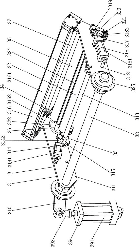
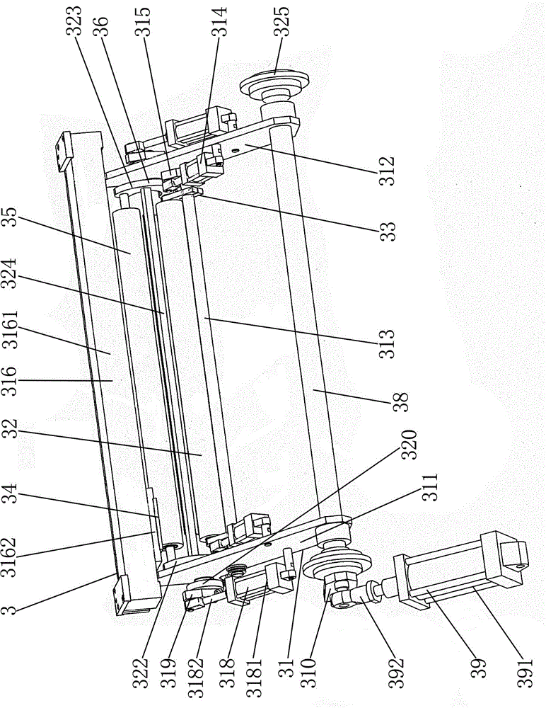
The invention provides a central winding machine. The central winding machine comprises a machine frame and an overturning frame, wherein the overturning frame can be installed on a machine frame in a rotating manner, and a first winding shaft and a second winding shaft are installed on the overturning frame. The central winding machine is characterized by further comprising a material receiving mechanism, wherein the material receiving mechanism comprises a material receiving frame, a press roll, a press roll frame, a cutting tool, a cutting tool translating mechanism, a chip roller and a chip roller frame, wherein the material receiving frame can be installed on the machine frame in a rotating manner, a material receiving frame oscillation control mechanism is arranged on the machine frame, the press roll frame is installed on the material receiving frame in a rotating manner, the press roll is installed on the press roll frame, a press roll oscillation control mechanism is arranged on the material receiving frame, the cutting tool translating mechanism is arranged on the material receiving frame, the cutting tool is connected to a power output end of the cutting tool translating mechanism, the chip roller frame is installed on the material receiving frame in a rotating manner, the chip roller is installed on the chip roller frame, and a chip roller oscillation control mechanism is arranged on the material receiving frame. According to the invention, as the material receiving mechanism is arranged, materials can be cut off and received automatically, automatic roll replacement and high roll replacing speed can be realized, and production efficiency can be increased.

Description

technical field [0001] The invention relates to winding equipment, in particular to a center winding machine with automatic roll changing function. Background technique [0002] The winder is used for winding sheets, films, paper and other materials. At present, most winders have two winding shafts, and the two winding shafts take turns to perform winding. [0003] An existing central winder includes a frame and a turning frame. The turning frame is rotatably mounted on the frame, and a first winding shaft and a second winding shaft are installed on the turning frame; An overturning drive mechanism for rack rotation, a first roll-up drive mechanism capable of driving the first roll-up shaft to rotate, and a second roll-up drive mechanism capable of driving the second roll-up shaft to rotate. Usually the first rewinding drive mechanism includes a first rewinding drive motor, and the power output shaft of the first rewinding drive motor is connected to the first rewinding sh...

Claims


Application Information

Patent Timeline
Patent Type & Authority Patents(China)
IPC IPC(8): B65H19/30B65H19/26B65H19/28
Inventor 罗庆青叶镇波
Owner SHANTOU DACHENG ENVIRONMENTAL PROTECTION PRECISION MACHINE TECH CO LTD
Learn More