
Industrial robot

A technology for industrial robots and components, applied in manipulators, metal processing, manufacturing tools, etc., can solve the problems of narrow application range, small size, large volume, etc., and achieve the effect of reliable and unmanned

Active Publication Date: 2014-09-10
刘朝龙
View PDF8 Cites 0 Cited by
  • Summary
  • Abstract
  • Description
  • Claims
  • Application Information

AI Technical Summary

Problems solved by technology

[0002] At present, the robots in the field of CNC machining on the market can only realize the functions of grasping and moving, and the degree of versatility is not high. Although there are many joints, they cannot grasp heavy workpieces, and the scope of application for grasping workpieces is small and narrow.
Although individual robots can grab heavy workpieces, they are bulky, occupy a large area, are relatively expensive, and have imperfect supporting facilities
Traditional industrial robots are generally equipped with conveyor belt systems for automated production. Ordinary conveyor belt systems occupy a large area and are the basic work unit for large-scale integrated control. They are limited to companies with complete workshop facilities and large plant areas. More importantly, parts The processing time between processes needs to be coordinated, otherwise it will be difficult to achieve. It is generally difficult to achieve consistent processing time between processing processes in the machinery industry, so it is not suitable for widespread use, and the conveyor belt system requires personnel to frequently discharge materials at the initial position according to the rhythm. At the end of the finished product, there must be a special person to properly arrange and inspect according to the rhythm to prevent parts from colliding. Therefore, if you purchase two or three robots and assign people to load and unload, it will not only fail to save manpower, but will increase costs. Today, there are many varieties of product parts and components of enterprises according to market demand. The real situation is that each enterprise only has corresponding parts suitable for robots. Purchasing traditional robots and conveyor belt systems is not cost-effective and meaningless. Therefore, it is necessary to improve

Method used


Image

  • Industrial robot
  • Industrial robot
  • Industrial robot

Examples


Embodiment Construction

[0055] An embodiment of the present invention is described below in conjunction with the accompanying drawings.

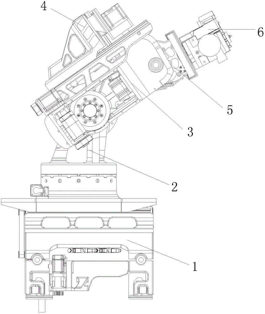
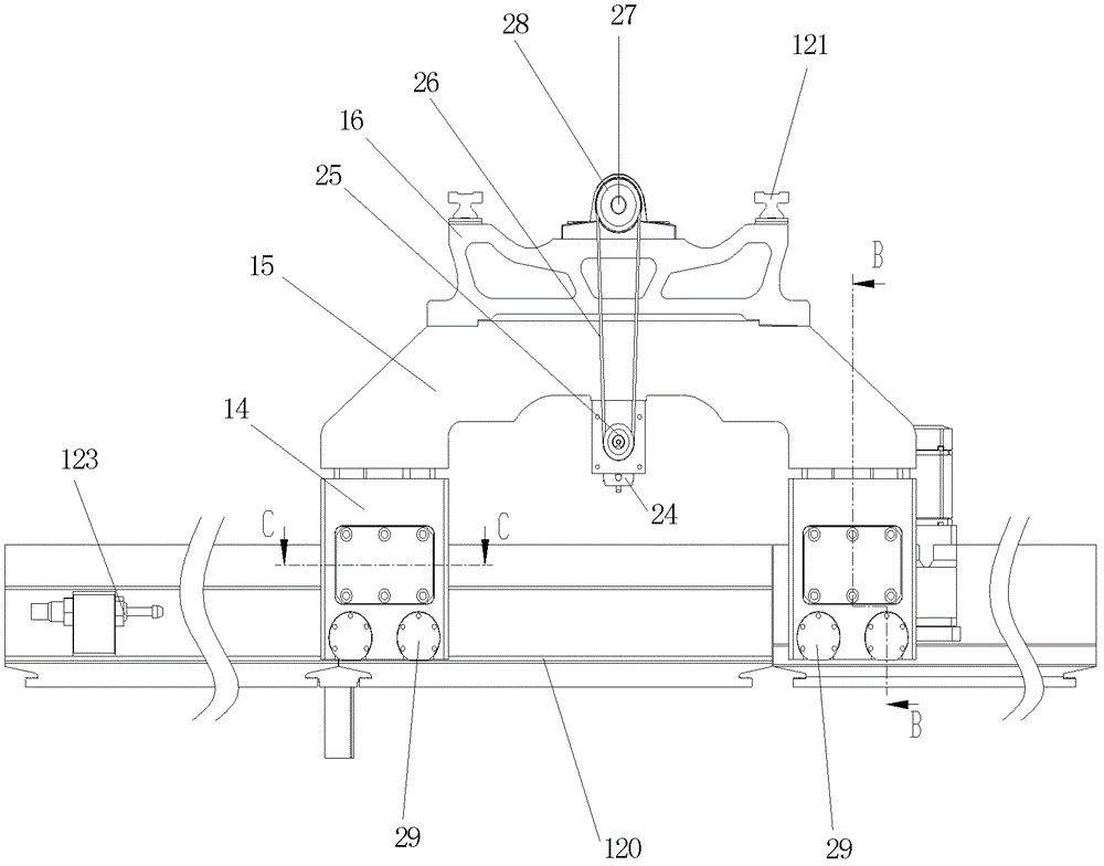
[0056] Such as figure 1 The shown industrial robot includes a base rail assembly 1, a base assembly 2, a boom assembly 3, an engraving and milling assembly 4, a wrist assembly 5 and a gripper assembly 6, and the lower end of the base rail assembly 1 is in contact with the guide rail 1 120 It is suitable and can roll along the guide rail I 120. The lower end of the base assembly 2 is adapted to the guide rail II 121 provided on the upper end of the base guide rail assembly 1 and can slide along the guide rail II 121. The base assembly 2 is composed of an upper assembly 7 and a lower assembly 8 , and the upper assembly 7 can rotate around the lower assembly 8; the shoulder shaft 9 on the boom assembly 3 is in floating fit with the shoulder shaft hole 10 on the upper part of the upper assembly 7, and the boom assembly 3 realizes the arm raising or lowering action; Th...


PUM


Abstract

The invention provides an industrial robot, which comprises a base guide rail component, a base component, a large arm component, an engraving and milling component, a wrist component and a claw component, wherein the lower end of the base guide rail component is matched with a guide rail I and can roll along the guide rail I; the lower end of the base component is matched with a guide rail II which is arranged at the upper end of the base guide rail component and can slide along the guide rail II; the base component consists of an upper component and a lower component, wherein the upper component can rotate around the lower component; a shoulder shaft on the large arm component is in floating fit with a shoulder shaft hole formed on the upper part of the upper component, and the large arm component realizes the action of lifting or lowering the arm; the lower part of the engraving and milling component is matched with a guide rail III which is arranged on the side of the large arm component, can slide along the guide rail III and realizes a drilling action; the wrist component is arranged in a mounting hole of the large arm component through a loop bar and finishes the action of lifting and lowering the wrist; and the side of the claw component is matched with a guide rail IV which is arranged on the wrist component, slides along the guide rail IV and realizes the action of opening and closing the claws.

Description

technical field [0001] The invention belongs to the technical field of mechanical processing robots, and in particular relates to an industrial robot. Background technique [0002] At present, the robots in the field of CNC machining on the market can only realize the functions of grasping and moving, and the degree of versatility is not high. Although there are many joints, they cannot grasp heavy workpieces, and the scope of application for grasping workpieces is small and narrow. Although individual robots can grab heavy workpieces, they are bulky, occupy a large area, are relatively expensive, and have imperfect supporting facilities. Traditional industrial robots are generally equipped with conveyor belt systems for automated production. Ordinary conveyor belt systems occupy a large area and are the basic work unit for large-scale integrated control. They are limited to companies with complete workshop facilities and large plant areas. More importantly, parts The proce...

Claims


Application Information

Patent Timeline
Patent Type & Authority Patents(China)
IPC IPC(8): B25J9/08B25J18/00B25J15/08B25J17/00B23Q7/04
Inventor 刘朝龙
Owner 刘朝龙
Learn More