Target and backing plate assembly

A backing plate and assembly technology, applied in ion implantation plating, coating, electrical components, etc., can solve the problems of high target use efficiency, arcing, and large changes in film forming speed, and achieve the generation of powder particles. Less, high efficiency, good uniformity

Active Publication Date: 2012-09-05
JX NIPPON MINING & METALS CO LTD
View PDF8 Cites 10 Cited by
  • Summary
  • Abstract
  • Description
  • Claims
  • Application Information

AI Technical Summary

Problems solved by technology

In this case, there is a problem that, since the initial erosion surface is not parallel to the substrate and the magnet arranged on the back side of the target, the flying particles during sputtering may become irregular (variable) from the initial stage to the middle stage. question
However, it is pointed out that a target of this shape (the target whose initial erosion surface is not parallel to the substrate and the magnet arranged on the back side of the target) has a problem that flying particles become irregular (variable) during sputtering.
That is, although the use efficiency is high, the following problems can also be expected: the change of the film forming speed during the use of the target is large, the number of occurrences of arcing is large, and the process loss rate is high.
According to this method, for a ceramic material having a thermal conductivity close to that of ITO, if the adhesion between the water-cooled plate (backing plate) and the holder is not complete, there is a possibility that the cooling during sputtering is insufficient, so the target may be generated. The problem that the possibility of failure such as rupture is high
[0017] From the above, it can be seen that the existing sputtering targets have not been designed from the viewpoints that the use efficiency of the target is high, uniform sputtering can be performed from the initial sputtering, and The target and the backing plate are simple in shape and easy to manufacture
In addition, there are also problems such as flashover

Method used


Image

  • Target and backing plate assembly
  • Target and backing plate assembly
  • Target and backing plate assembly

Examples


Embodiment 1

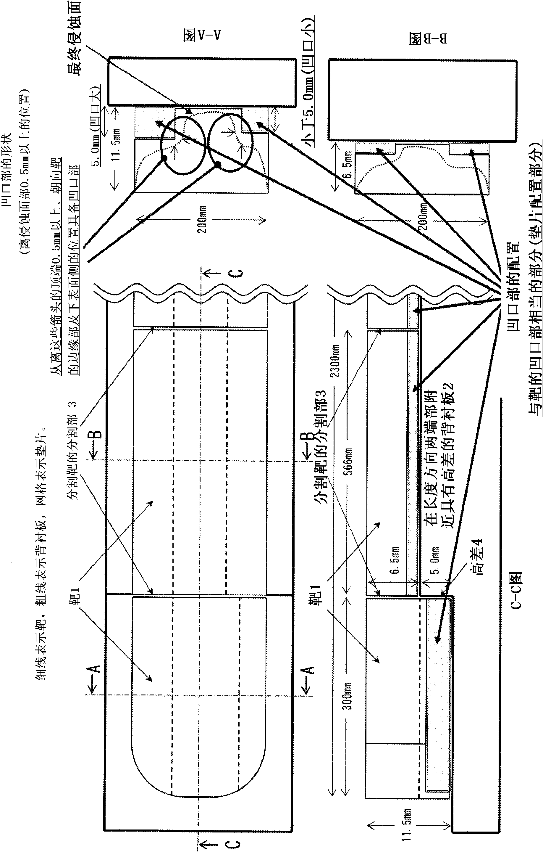
[0079] use figure 1 In the shown copper backing plate and target, ITO (indium tin oxide) was used as the target. figure 1 A plan view (part), C-C sectional view, A-A sectional view, and B-B sectional view of the target-backing plate assembly are shown. as it should figure 1 As shown, the backing plate of the target-backing plate assembly of Example 1 is rectangular (rectangular) in plan view, and both ends in the longitudinal direction of the target are elliptical. In this case, a split target is used. The bottoms of both sides in the longitudinal direction of this divided target are left-right asymmetrical in the longitudinal direction.

[0080] As for the backing board, a backing board having a thickness of 5.0 mm on both sides in the longitudinal direction, that is, a backing board having a height difference of 5.0 mm was used. Copper spacers with a thickness of 4.5 mm and a thickness of 5.0 mm were placed on the height difference portion, that is, the thin side of t...

Embodiment 2

[0126] use Figure 8 In the shown copper backing plate and target, ITO (indium tin oxide) was used as the target. Figure 8 A plan view (part), C-C sectional view, A-A sectional view, and B-B sectional view of the target-backing plate assembly are shown. as it should Figure 8 As shown, the backing plate of the target-backing plate assembly of Example 2 is rectangular (rectangular) in plan view, and both ends in the longitudinal direction of the target are elliptical. In this case, a split target is used. The bottoms of both sides in the longitudinal direction of this split target are asymmetrical in the longitudinal direction (concavo-convex shape) similarly to Example 1. As the backing board, a backing board whose entire surface is flat is used.

[0127] And, as the targets on both sides in the longitudinal direction, those having notches of 4.5 mm and 5.0 mm on the side of the backing plate were used. Then, spacers made of copper with a thickness of 4.5 mm and a thickn...


PUM


Abstract

A target and backing plate assembly for magnetron sputtering includes a target, the distance between the erosion surface of the target and a magnet disposed at the rear surface of the target and that between the erosion surface and a surface of a substrate facing the target being fixed. The target has an uneven shape of which thickness is changed at a surface adjacent to a backing plate such that portions to be eroded by sputtering are thick. Conductive spacers are disposed between the backing plate and the target having the uneven shape at thin portions of the target. With this structure, a target of which lifetime and use efficiency are increased while film uniformity (uniformity of film thickness) is kept excellent throughout the sputtering life of the target can be provided. In addition, a method of manufacturing the target and a target backing plate can be provided.

Description

technical field [0001] The present invention provides a target-backing plate assembly that can prolong the life of a target and can make film uniformity (uniformity of film thickness) good throughout the sputtering process, and Even if there is a difference in erosion depending on the type of target material, a high-use-efficiency target corresponding to the inherent target erosion can be easily manufactured. Background technique [0002] The method of forming a thin film by sputtering is widely used in the manufacture of various electronic and electrical components. [0003] The principle used by the sputtering method is as follows: the substrate as a positive electrode is opposed to the target as a negative electrode, and a high voltage is applied between the substrate and the target in an inert gas atmosphere to generate an electric field. At this time, ionized electrons and The plasma is formed by the collision of the inert gas, and when positive ions in the plasma coll...

Claims


Application Information

Patent Timeline
Patent Type & Authority Applications(China)
IPC IPC(8): C23C14/34
CPCC23C14/086C23C14/3407C23C14/35H01J37/3405H01J37/3423H01J37/3435H01J37/3482C23C14/34
Inventor 熊原吉一
Owner JX NIPPON MINING & METALS CO LTD
Why Eureka
Try Eureka