Method for determining design values for crystal oscillator circuit and electronic apparatus

A technology of quartz oscillation and design value, applied in the direction of power oscillators, electrical components, etc., can solve the problems of easy IC design, etc., and achieve the effects of easy design, realization of driving current, and realization of miniaturization

Inactive Publication Date: 2012-08-22
SEIKO INSTR INC
View PDF1 Cites 2 Cited by
  • Summary
  • Abstract
  • Description
  • Claims
  • Application Information

AI Technical Summary

Problems solved by technology

However, when designing an IC, the drive current value of the crystal oscillator circuit can be estimated in advance, which makes IC design easy.

Method used


Image

  • Method for determining design values for crystal oscillator circuit and electronic apparatus
  • Method for determining design values for crystal oscillator circuit and electronic apparatus
  • Method for determining design values for crystal oscillator circuit and electronic apparatus

Examples


Embodiment Construction

[0052] The object of the present invention is to provide a clear relationship between the drive current Ios of a crystal oscillator circuit using a quartz oscillator, the value of the load capacitance CL and the negative resistance RL, and to determine what level of load capacitance to use in order to design the required drive current Ios The CL value and the negative resistance RL value are suitable methods.

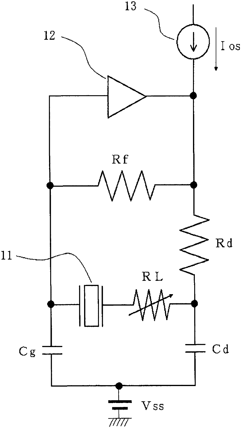
[0053] figure 1 It is a diagram showing a measurement circuit used in order to clarify the relationship between the drive current Ios, the load capacitance CL, and the negative resistance RL in a crystal oscillation circuit using a crystal oscillator. basically and Figure 9 In the same figure, as the crystal vibrator 11, a crystal vibrator SSP-T7-FL (basic frequency: 32.768 KHz) made by SII was used. 12 is a CMOS inverter, and 13 is a constant current source, so that a constant current (this current is the driving current Ios) flows into the quartz oscillator circuit...


PUM


Abstract

The present invention aims to providing a method for determining design values for a quartz oscillating circuit, through using a relation of load capacitance CL, negative resistance RL and drive current Ios of the oscillating circuit of a quartz oscillator. The third value can be determined through using a relation formula or a relation curve after determining two values of the negative resistance RL, the load capacitance CL and the drive current Ios, in the process of using the quartz oscillating circuit of the quartz oscillator.

Description

technical field [0001] The present invention relates to a design value determination method and electronic equipment of a quartz (crystal) oscillation circuit. Background technique [0002] In portable devices such as clocks and mobile phones, since the device is required to be able to operate for a long time in a non-charging state or to reduce the charging frequency of the mounted battery, it is increasingly necessary to reduce the quartz vibration used in the device. Ultra-low power consumption of the oscillation circuit driving power of piezoelectric elements such as piezoelectric devices or when the oscillation circuit is in standby (when the oscillation circuit is in an oscillation state and no load state). [0003] Figure 9 It is a typical oscillation circuit using a crystal oscillator. It has a CMOS inverter IV01 used as an inverting amplifier, a crystal oscillator X2 connected between the input terminal XCIN and the output terminal XCOUT of the CMOS inverter IV01, ...

Claims


Application Information

Patent Timeline
Patent Type & Authority Applications(China)
IPC IPC(8): H03B5/32H03B5/06
CPCH03B5/364
Inventor 相马弘之
Owner SEIKO INSTR INC
Why Eureka
Try Eureka