Bridge type tool for measuring high-precision camera mounting surface

A mounting surface, high-precision technology, applied in artificial horizontal plane and other directions

Active Publication Date: 2014-06-25
SHANGHAI INST OF SATELLITE EQUIP
View PDF5 Cites 0 Cited by
  • Summary
  • Abstract
  • Description
  • Claims
  • Application Information

AI Technical Summary

Problems solved by technology

From the measurement envelope and measurement accuracy, it can be seen that the traditional marble platform measurement method is no longer suitable for the measurement here

Method used


Image

  • Bridge type tool for measuring high-precision camera mounting surface
  • Bridge type tool for measuring high-precision camera mounting surface
  • Bridge type tool for measuring high-precision camera mounting surface

Examples


Embodiment Construction

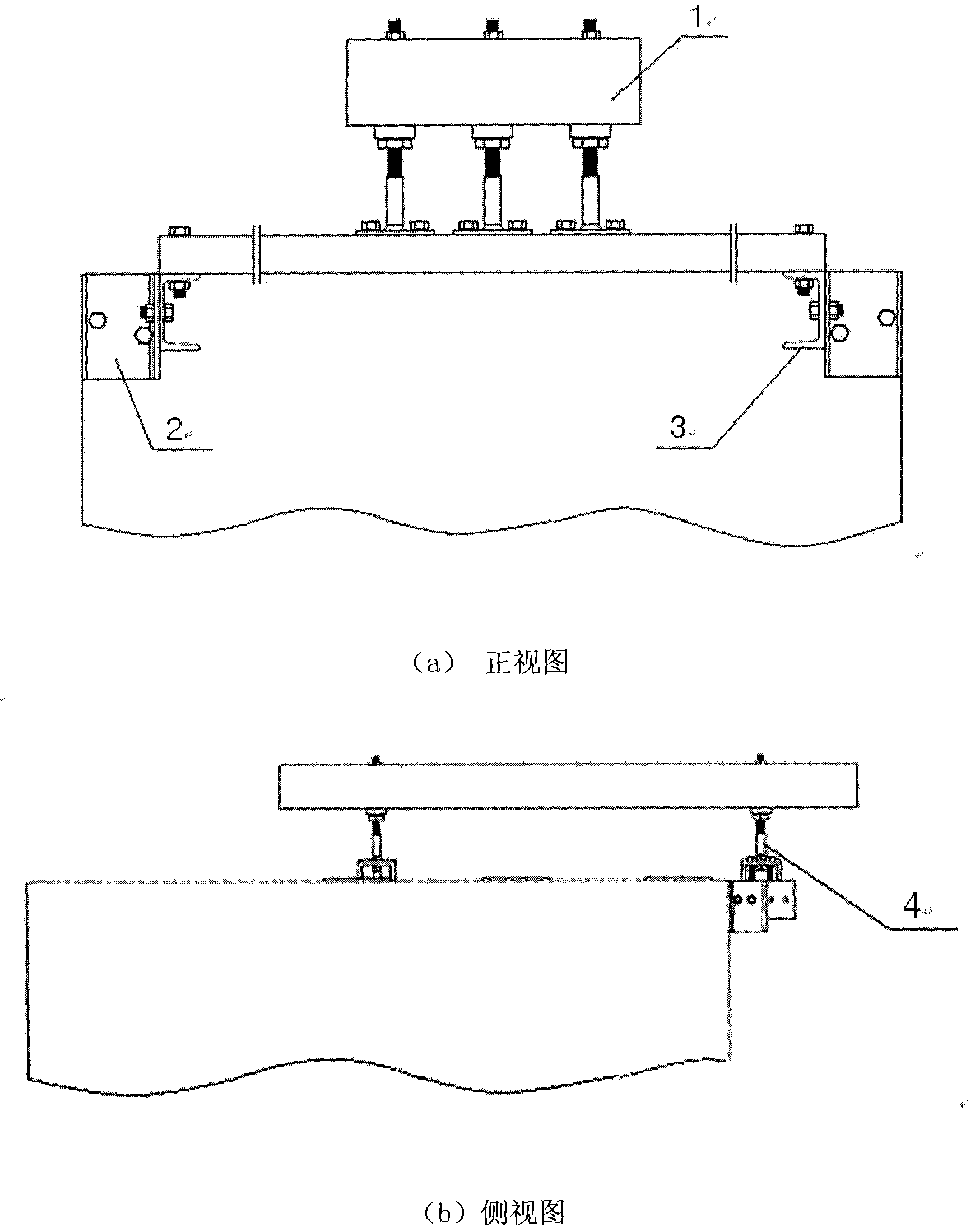
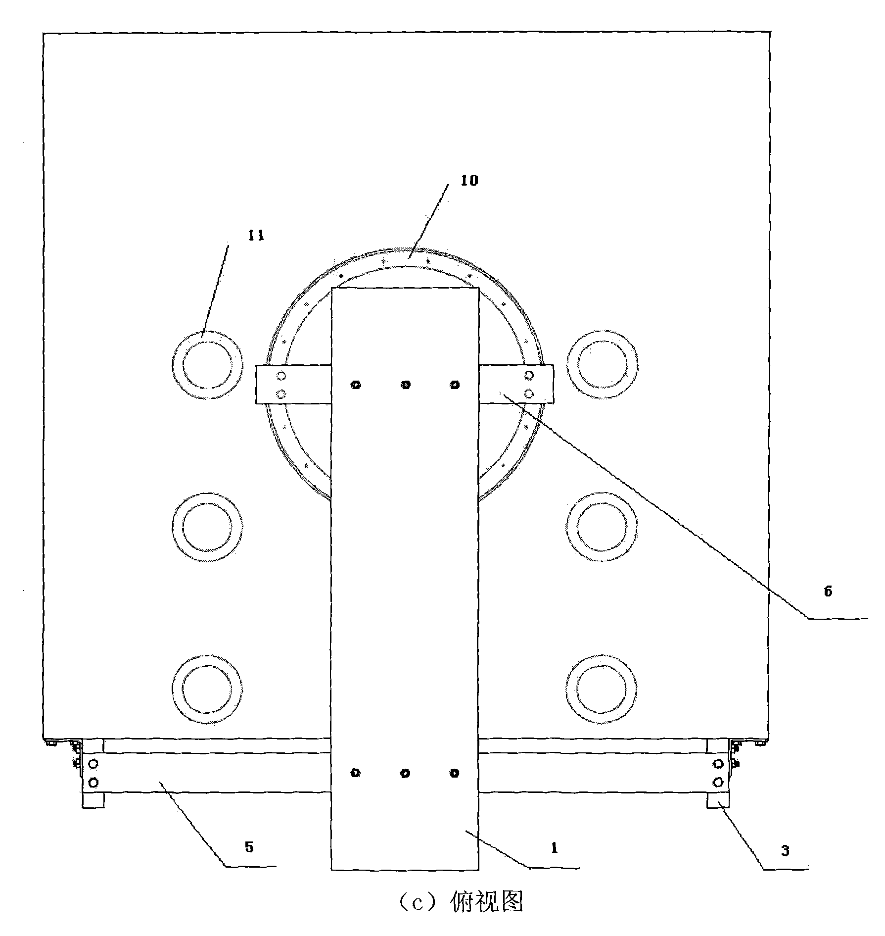
[0019] like figure 2 and image 3 As shown, a bridge-type tooling for measuring the installation surface of a high-precision camera is composed of a parallel gauge 1, an angle piece 2, a channel steel 3, a support and levelness adjustment device 4, a long support beam 5, a short support beam 6, a spacer 7, Support rod 8 and fasteners are formed. Among them, the angle piece 2 is connected with the side plate of the structure to be measured through two sets of fasteners, the channel steel 3 is connected with the angle piece 2 through two sets of fasteners, and the long support beam 5 is connected with two sets of fasteners through four sets of fasteners. The channel steel is connected. The six support and levelness adjusting devices 4 are respectively connected with the long and short support beams by two sets of fasteners. The short support beam 6 is connected to the load-bearing cylinder of the structure to be measured through pads 7 and support rods 8 . The parallel gaug...


PUM


Abstract

The invention relates to a bridge type tool for measuring a high-precision camera mounting surface, which consists of a parallel ruler (1), an angle piece (2), a U-bar (3), a support and levelness regulating device (4), a long support beam (5), a short support beam (6), a cushion block (7), a support rod (8) and a fastening piece; and under the premise of satisfying the high precision requirement on measuring the mounting surface, a measuring datum is transferred from the ground to the parallel ruler at the upper part of a top plate, so the problem that measure within a big envelope scope cannot be realized by using the traditional method is solved.

Description

technical field [0001] The invention relates to a tool for measuring the mounting surface, more particularly, to a bridge tool for measuring the mounting surface of a high-precision camera. Background technique [0002] A product with high precision requirements needs to establish benchmarks during the development process. In order to ensure the datum and other precision requirements, it is required to adjust to a high level after being combined with process auxiliary equipment. Combined fixtures, contour blocks, and jacks are commonly used support devices, and some special equipment requires special support devices to adjust their levelness. [0003] A product requires a camera to be mounted on the top plate, such as figure 1 As shown, the mounting points reserved on the top plate are six annular bosses, and there is a certain span between the bosses in the horizontal / vertical direction, and the vertical height between the top plate and the ground is not more than 1400mm....

Claims


Application Information

Patent Timeline
Patent Type & Authority Patents(China)
IPC IPC(8): G01C15/14
Inventor 张则梅袁佳晶徐水涌
Owner SHANGHAI INST OF SATELLITE EQUIP
Why Eureka
Try Eureka