Energy-conservation high-efficiency reduction sponge iron tunnel kiln

A technology of sponge iron and tunnel kiln, which is applied to furnaces, furnace types, fluidized bed furnaces, etc., can solve the problems of changing one-way single-lane vehicle entry mode, difficult to control pressure and atmosphere, and large footprint, and achieve beneficial results. For preheating and cooling, compact structure, small footprint effect

Inactive Publication Date: 2012-08-22
黄冈市中基窑炉有限公司
View PDF1 Cites 1 Cited by
  • Summary
  • Abstract
  • Description
  • Claims
  • Application Information

AI Technical Summary

Problems solved by technology

Another example is that after the kiln is extended, the pressure and atmosphere in the kiln are not easy to control, and it is very difficult to operate
To solve these problems, on the one hand, it is necessary to increase the fire path between the refractory tanks. Due to the addition of fire paths on a single kiln car, there will be unstable factors when stacking refractory tanks, and it is easy to pour the tanks; on the other hand, it is necessary to change the one-way single-lane entry mode
At the same time, the current tunnel kiln generally adopts a three-zone division model, namely, the preheating section, the reduction section and the cooling section. Auxiliary facilities need to be built outside the kiln, such as tow lanes, return lines, and loading and unloading areas. Such a kiln body structure not only exists It occupies a large area, and in order to save energy, it is necessary to install a waste heat recovery device on the kiln body to recover and reuse the waste heat in the cooling section of the kiln body

Method used


Image

  • Energy-conservation high-efficiency reduction sponge iron tunnel kiln
  • Energy-conservation high-efficiency reduction sponge iron tunnel kiln
  • Energy-conservation high-efficiency reduction sponge iron tunnel kiln

Examples


Embodiment Construction

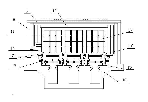
[0010] As shown in the figure, take the company’s construction of a direct reduction iron tunnel kiln with an annual output of 50,000 tons as an example. I-shaped steel is used to make upright columns 8 on both sides of the kiln body and channel steel is used to make top beams 9 to form a frame. The brick structure is built between the columns 8 to form a kiln wall 11. The thickness of the kiln wall is 930 mm. Hanging pieces and hooks are used to build the ceiling bricks in the top beam 9 to form a kiln roof 10. The thickness of the kiln roof is 360 mm. The kiln is 86.53 meters long, the inner width of the kiln cavity is 5228 mm, and the inner height is 1972 mm. On the kiln wall 11, holes 14 for installing burners are set according to the distribution of burners in the combustion system. It is built with bricks 12, and the kiln foundation 18 at the bottom of the kiln cavity is provided with six rows of rails 15 for the kiln car 16 to run side by side with three lanes. Among th...


PUM


Abstract

The invention discloses an energy-conservation high-efficiency reduction sponge iron tunnel kiln, which solves the problem that the existing direct reduction iron tunnel kiln is generally big in land occupation, low in volume of production, not apt to completely restore the sponge iron in the middle of a wide section tunnel kiln car, difficult in quality guarantee and the like. The energy-conservation high-efficiency reduction sponge iron tunnel kiln is characterized in that a kiln body is a wide section structure, three car lanes side by side for walking of common kiln cars (16) are formed by six rows of tracks (15) and arranged at the bottom of a kiln cavity, only a preheat cooling section (5) and a reduction section (6) are arranged on the front and the back of the kiln body, carrying lanes (4 and 7) are respectively arranged at the kiln head and the kiln tail, an unloading area (3) and a loading area (2) are arranged in front of the kiln head carrying lane (4), and a carrying lane (1) is arranged on the end portion of the loading area (2). The energy-conservation high-efficiency reduction sponge iron tunnel kiln is compact in structure, reasonable in overall arrangement, simple in operation, small in occupation, low in energy consumption, high in output and the like, and capable of widely applying to manufacturing enterprises of direct reduction sponge iron.

Description

1. Technical field [0001] The invention belongs to smelting equipment, in particular to an energy-saving and high-efficiency reducing sponge iron tunnel kiln. 2. Background technology [0002] With the continuous development of science and technology, in order to meet the needs of the large-scale development of direct reduction iron tunnel kiln production, the development trend of direct reduction sponge iron tunnel kiln is that the kiln is long and wide. However, simply lengthening and widening is difficult to solve problems in actual production, and there are many disadvantages. For example, after the kiln is widened, the kiln car will also be widened accordingly, and the density of the refractory tank on the kiln car will increase, so the sponge iron in the middle of the kiln car will not be fully reduced and the phenomenon will appear. Another example is that after the kiln is extended, the pressure and atmosphere in the kiln are not easy to control, and it is very diff...

Claims


Application Information

Patent Timeline
Patent Type & Authority Applications(China)
IPC IPC(8): C21B13/00
Inventor 陈正东
Owner 黄冈市中基窑炉有限公司
Why Eureka
Try Eureka