Workpiece support

A workpiece and support technology, applied in the field of workpiece support, can solve the problem of inflexible workpiece support

Active Publication Date: 2012-08-22
J SCHMALZ GMBH
View PDF5 Cites 0 Cited by
  • Summary
  • Abstract
  • Description
  • Claims
  • Application Information

AI Technical Summary

Problems solved by technology

However, this workpiece support is very inflexible, because it ...

Method used


Image

  • Workpiece support
  • Workpiece support

Examples


Embodiment Construction

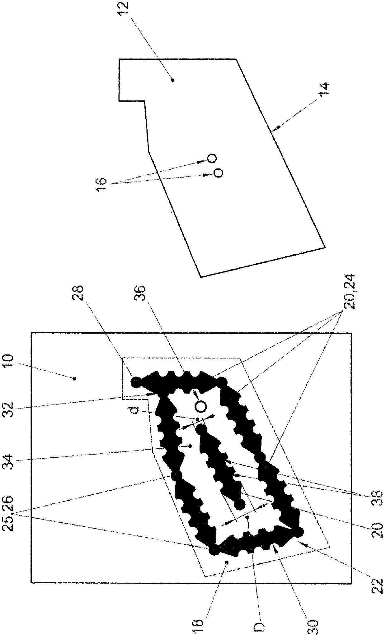
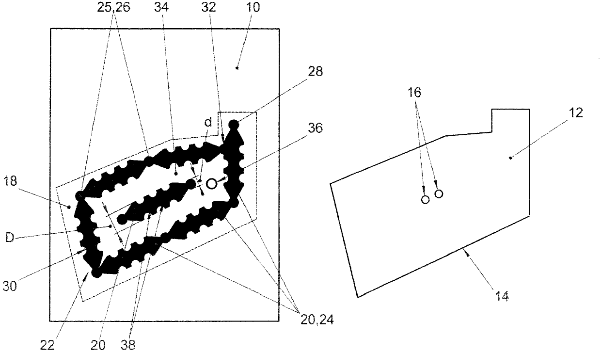
[0018] This figure shows a support table, generally designated 10 , which is made of ferromagnetic material. Next to the support table is shown the workpiece to be processed, indicated as a whole by 12 , which is made, for example, of plastic, metal, wood or a wood-like material. The workpiece 12 has an irregular outer contour 14 and has a flat underside. Furthermore, two openings 16 can be seen, which have to be produced or machined.

[0019] The outer contour 14 of the workpiece 12 is shown on the support table 10 with dashed lines 18 , and a workpiece support 22 comprising a plurality of support elements 20 can be seen, on which the workpiece 12 for machining rests. It is clearly visible that the workpiece support 22 supports the workpiece 12 optimally and that the edges of the workpiece 12 protrude beyond the workpiece support 22 on all sides.

[0020] As already mentioned, the workpiece carrier 22 comprises a plurality of support elements 20 which are suspended on one a...


PUM

PropertyMeasurementUnit
Heightaaaaaaaaaa

Abstract

The workpiece support (22) comprises a primary side facing a support table (10) and a secondary side facing a workpiece (12). The primary side facing the support table is partially magnetic. The secondary side facing the workpiece or the primary side facing the support table is coated with plastic in sections, particularly an elastomer. The workpiece support is coated on all sides with plastic, particularly an elastomer.

Description

technical field [0001] The invention relates to a workpiece support having a first side facing the support table and a second side facing the workpiece. Background technique [0002] In order to be able to clamp, in particular plate-shaped workpieces on the support table of a processing machine for subsequent processing, vacuum cutting devices are often used which grip only the underside of the workpiece so that the upper side and the side edges Available for processing. Between the support table and the tool there is then usually a workpiece holder, which closes the suction chamber in an airtight manner, so that it can be charged with a negative pressure, whereby the workpiece is sucked into and fixed to the holder superior. [0003] The company SCM discloses a workpiece support that has a frame-like structure and is formed from a plurality of support elements. These workpiece supports have a rubberized coating on their outer sides which protrudes slightly on the side di...

Claims


Application Information

Patent Timeline
IPC IPC(8): B23Q3/00
CPCB25B11/002
Inventor 拉尔夫·斯托克伯格
Owner J SCHMALZ GMBH
Why Eureka
Try Eureka