Loading base arrangement

A technology of bottom plate and locking device, which is applied to vehicles with easy-to-detachable loading components, transportation and packaging, detachable/non-detachable seats, etc., and can solve problems such as multi-space, space obstruction, and height restrictions on loading volume

Inactive Publication Date: 2008-12-17
GM GLOBAL TECH OPERATIONS LLC
View PDF1 Cites 0 Cited by
  • Summary
  • Abstract
  • Description
  • Claims
  • Application Information

AI Technical Summary

Problems solved by technology

[0003] The disadvantage of this load floor construction is that the folded rear seats require relatively much space in the vertical direction, so that the load volume is considerably limited in height
Especially when the rear seat is ergonomically shaped, for example, to improve comfort, such a load floor design is disadvantageous because the available space is hindered particularly greatly in the folded position of the rear seat.

Method used


Image

  • Loading base arrangement
  • Loading base arrangement
  • Loading base arrangement

Examples


Embodiment Construction

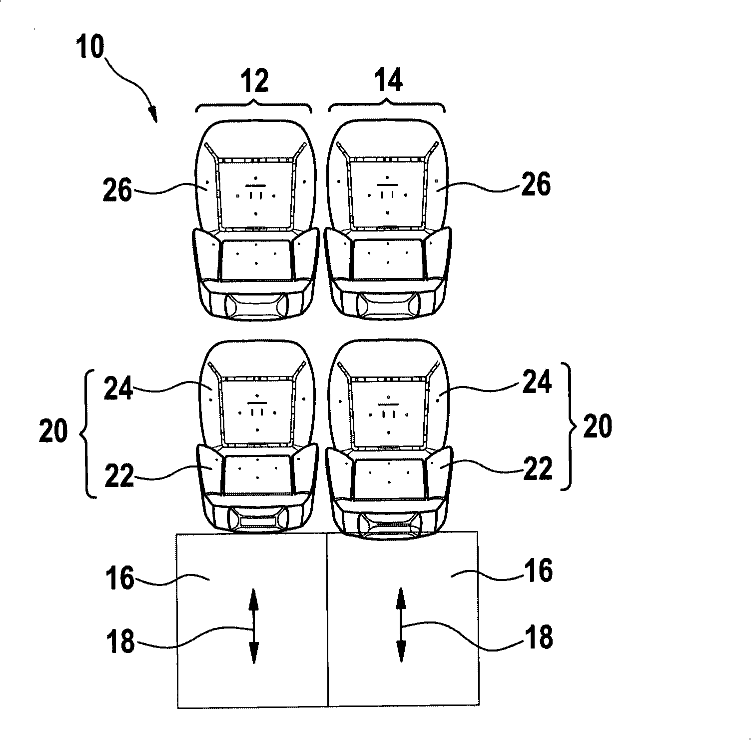
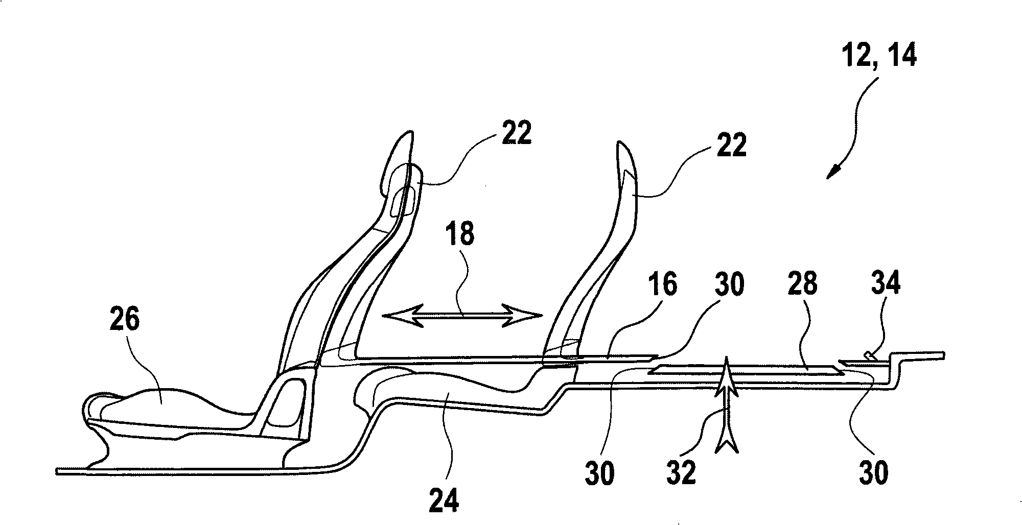
[0022] exist figure 1 In the vehicle interior 10 shown, a first loading floor structure 12 and a second loading floor structure 14 are arranged. The first load floor structure 12 is arranged on the driver's side, and the second load floor structure 14 is arranged on the passenger side. The loading floor structures 12 , 14 each have a floor element 16 movable in the direction of travel, which is displaceable in the direction of the arrow 18 . In each case a rear seat 20 is arranged in front of the floor element 16 , which has a backrest 22 and a seat cushion 24 .

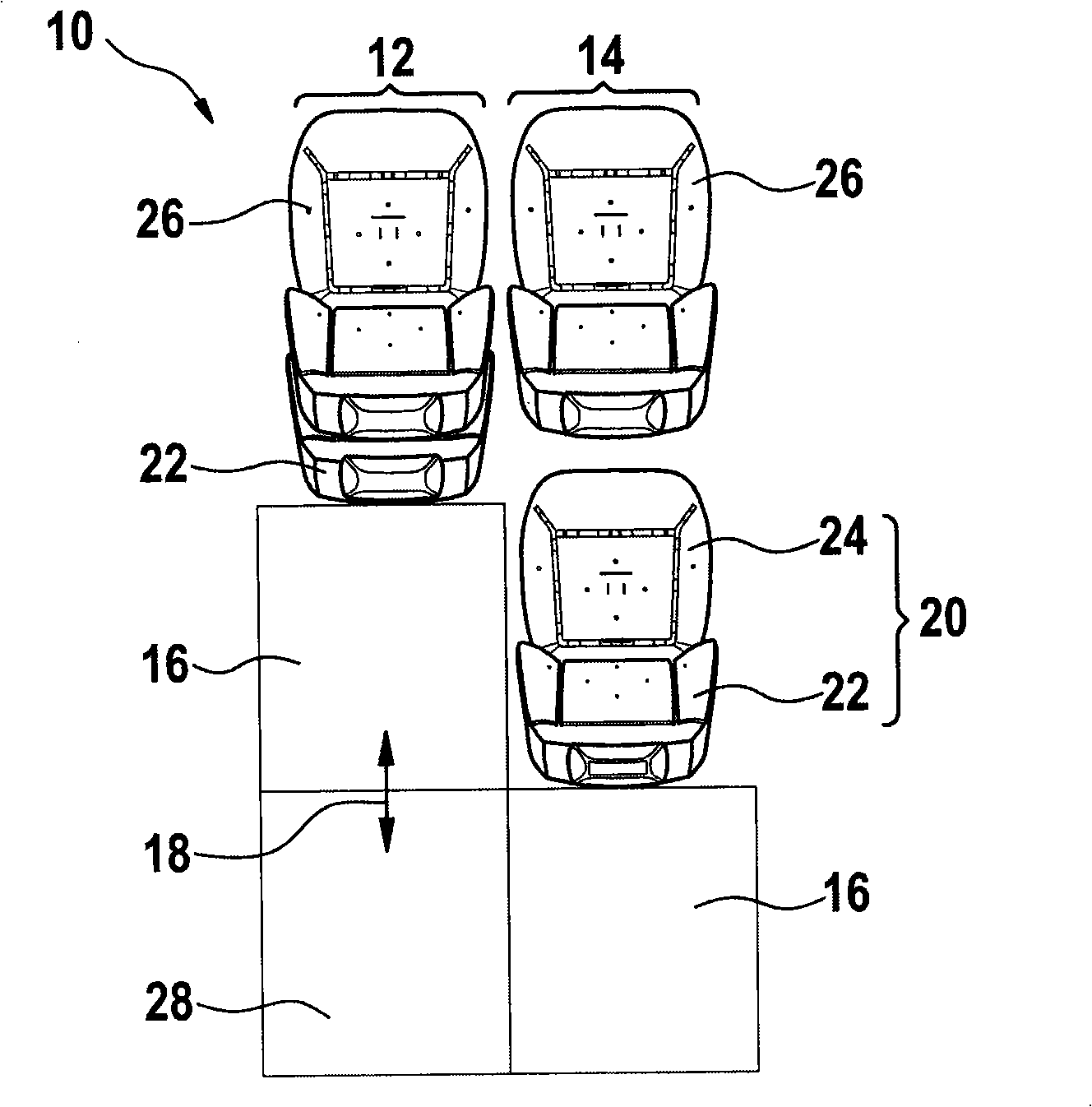
[0023] The backrest 22 is connected to the floor element 16 so that the backrest 22 moves together with the floor element 16 when the floor element 16 moves in the direction of the arrow 18 . exist figure 2 In the case of the loading floor structure 12 shown in the fully extended state, the floor element 16 is drawn out so far that the backrest 22 lies against the front seat 26 . An additional floor 28 is arrang...


PUM


Abstract

A loading bottom plate structure (12, 14) for automobile comprises a backseat (20) with a backrest (22) and a cushion (24). In addition, a bottom plate element (16) capable of moving along the running direction of the automobile is provided for receiving an object. The bottom plate element (16) is connected with the backrest (22) and covers the cushion (24) under the withdrawing state of the bottom plate element (16). Thereby, the loading space for transporting the object with large volume can be enlarged if necessary.

Description

technical field [0001] The invention relates to a loading floor structure for a motor vehicle, by means of which the loading space of the motor vehicle can be varied. Background technique [0002] DE 103 17 537 A1 discloses a loading floor structure for a motor vehicle in which a rear seat with a backrest and a seat cushion is arranged. In order to increase the loading space of the motor vehicle, the backrest can be folded onto the seat cushion, so that a floor element movable in the direction of travel and on which objects can be placed can be pulled out from above the folded rear seat. [0003] A disadvantage of this construction of the load floor is that the folded rear seat requires relatively much space in the vertical direction, so that the load volume is greatly limited in height. Such a load floor configuration is disadvantageous, in particular if the rear seat is ergonomically shaped, for example, to improve comfort, since the available space is impeded to a partic...

Claims


Application Information

Patent Timeline
IPC IPC(8): B60N2/36B60P1/64B60R11/00B60R7/00
CPCB60N2/3022B60R7/08B60R13/013B60R2013/016B60N2002/363B60N2/36B60N2/30
Inventor 克拉伦斯·金鲍里斯·雅各布
Owner GM GLOBAL TECH OPERATIONS LLC
Why Eureka
Try Eureka