
control the machine

A technology for machines and light sources, which is applied to cabinets/cabinets/drawer parts, cooling/heating devices for lighting devices, lighting devices, etc., and can solve the problems of complex structures and inability to ensure the space for configuring the grounding member 107, etc.

Active Publication Date: 2015-11-25
YAMATAKE HONEYWELL CO LTD
View PDF5 Cites 0 Cited by
  • Summary
  • Abstract
  • Description
  • Claims
  • Application Information

AI Technical Summary

Problems solved by technology

[0009] However, in the control device 100 disclosed in Patent Document 1, the grounding member 107 must be arranged. In the case of using a small control device, there is a problem that the space for disposing the grounding member 107 cannot be ensured. structurally complex issues

Method used


Image

  • control the machine
  • control the machine
  • control the machine

Examples


Embodiment Construction

[0018] Hereinafter, embodiments of the present invention will be described in detail with reference to the drawings.

[0019] (Embodiment 1)

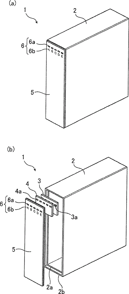
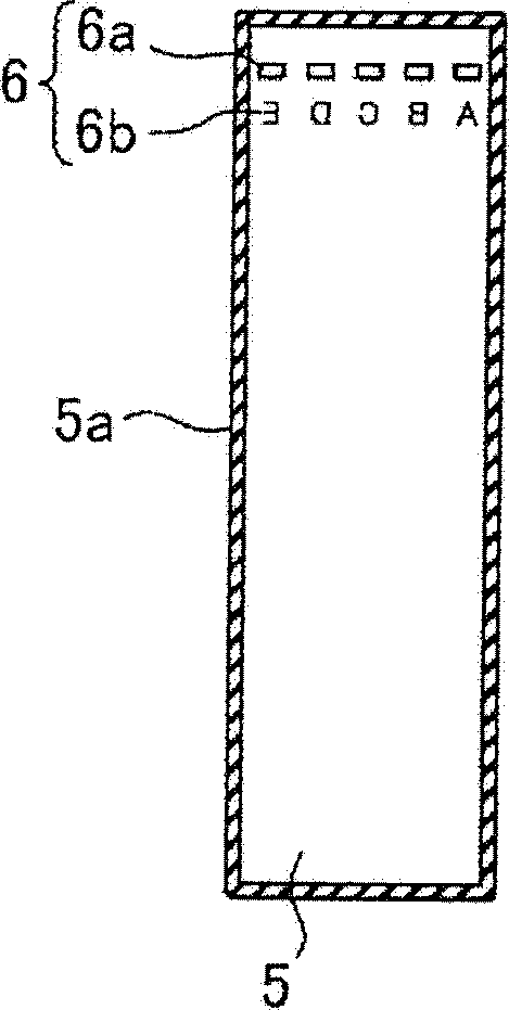
[0020] figure 1 It is a figure showing the structure of the control apparatus 1 of Embodiment 1 of this invention, figure 1 (a) is a stereogram, figure 1 (b) is an exploded perspective view. again, figure 2 It is a figure which shows the back surface of the surface panel 5 which concerns on Embodiment 1 of this invention.

[0021] Such as figure 1 As shown, the control device 1 is composed of a main body case 2 , a substrate 3 , a light guide member 4 , and a surface panel 5 . In addition, the color of the control device 1 is unified with black.

[0022] The main body case 2 is a case for accommodating the substrate 3 , the light guide member 4 , and a control circuit (not shown), and is made of black resin formed in a box-like shape with an opening at the front. A stepped frame portion 2 a for arranging the substrate 3 is ...


PUM


Abstract

A control apparatus is provided with a substrate disposed inside a main case and on which light sources are mounted. A surface panel in which light-source display windows are formed at positions opposite the light sources, is also disposed in the main case. The outer rim of the surface of the surface panel facing the main case is affixed to the front-surface rim of the main case with an insulating part sandwiched therebetween.

Description

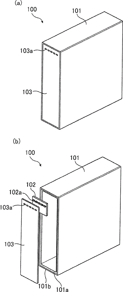
technical field [0001] The present invention relates to a control device for displaying the operating status of the device body on a surface panel by flickering a light source mounted on a substrate arranged inside, for example. Background technique [0002] The conventional control machine 100, such as image 3 As shown, a board 102 on which a light source 102 a such as an LED (Light Emitting Diode) that emits light corresponding to a predetermined operation of the control device 100 is mounted inside a main body case 101 . Also, on the front side of the main body case 101, a surface panel 103 having a light source display window 103a for displaying the operation status of the control device 100 and the like is formed at a position facing the light source 102a. The control device 100 configured in this way blinks the corresponding light source 102a according to the operation status, so that the manager can visually confirm the current operation status of the control device ...

Claims


Application Information

Patent Timeline
Patent Type & Authority Patents(China)
IPC IPC(8): H05K5/02F21V29/15
CPCH05K9/0067H05K5/0243F21V29/15
Inventor 内海庆也原田英史古贺宏
Owner YAMATAKE HONEYWELL CO LTD
Learn More