


Quick Research
Generate reliable direction feasibility study reports for your R&D in just a few steps.

Technical Q&A
Discover and master advanced knowledge NOW. Basics, ideas, possibilities, all at once.

Find Solutions
As an expert in R&D theories, this can generate solutions to your technical problems instantly.

Evaluate Feasibility
Analyze your overall solution with one click, know your potential R&D risks in advance.

Monitor Landscape
Get weekly tech updates, stay abreast of the latest tech innovations and key insights.
Adjustable kiln car
An adjustable kiln car technology, applied in the kiln car field, can solve the problems of inconvenient operation, labor and time-consuming, etc., and achieve the effects of good energy saving, strong flame penetration, and reduced energy consumption
- Summary
- Abstract
- Description
- Claims
- Application Information
AI Technical Summary
Problems solved by technology
Method used
Image

Examples
Embodiment 1
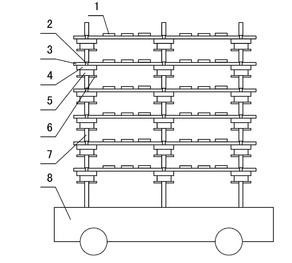
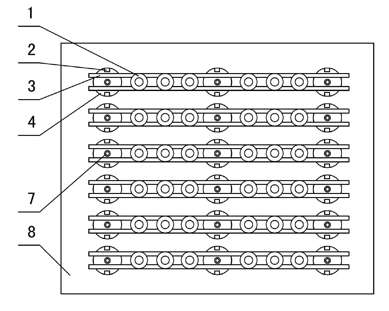
[0018] Such as figure 1 , figure 2 As shown, the adjustable kiln car includes a car body 8 on which multiple rows and rows of uprights 7 are fixed, and the uprights 7 are provided with multi-layer crossbeams spaced apart from each other in height, and each layer of crossbeams includes multiple rows of crossbeams 3. A multi-layer support body 4 is set on the column 7, a pin shaft 6 is arranged under the support body 4, an adjustment sleeve 5 is arranged between the support body 4 and the pin shaft 6, and the adjustment sleeve 5 is set on the column 7 , the pin shaft 6 is worn on the column 7, the crossbeam 3 is placed on the upper part of the support body 4, and the backing plate 1 is placed on the adjacent crossbeam 3 on the same layer.
[0019] In this embodiment, stoppers 2 are arranged correspondingly on both sides of the top of the support body 4, and the crossbeam 3 is arranged between the stoppers 2 and the columns 7. The crossbeam 3 is worn in the fixed sleeve; the b...
Embodiment 2
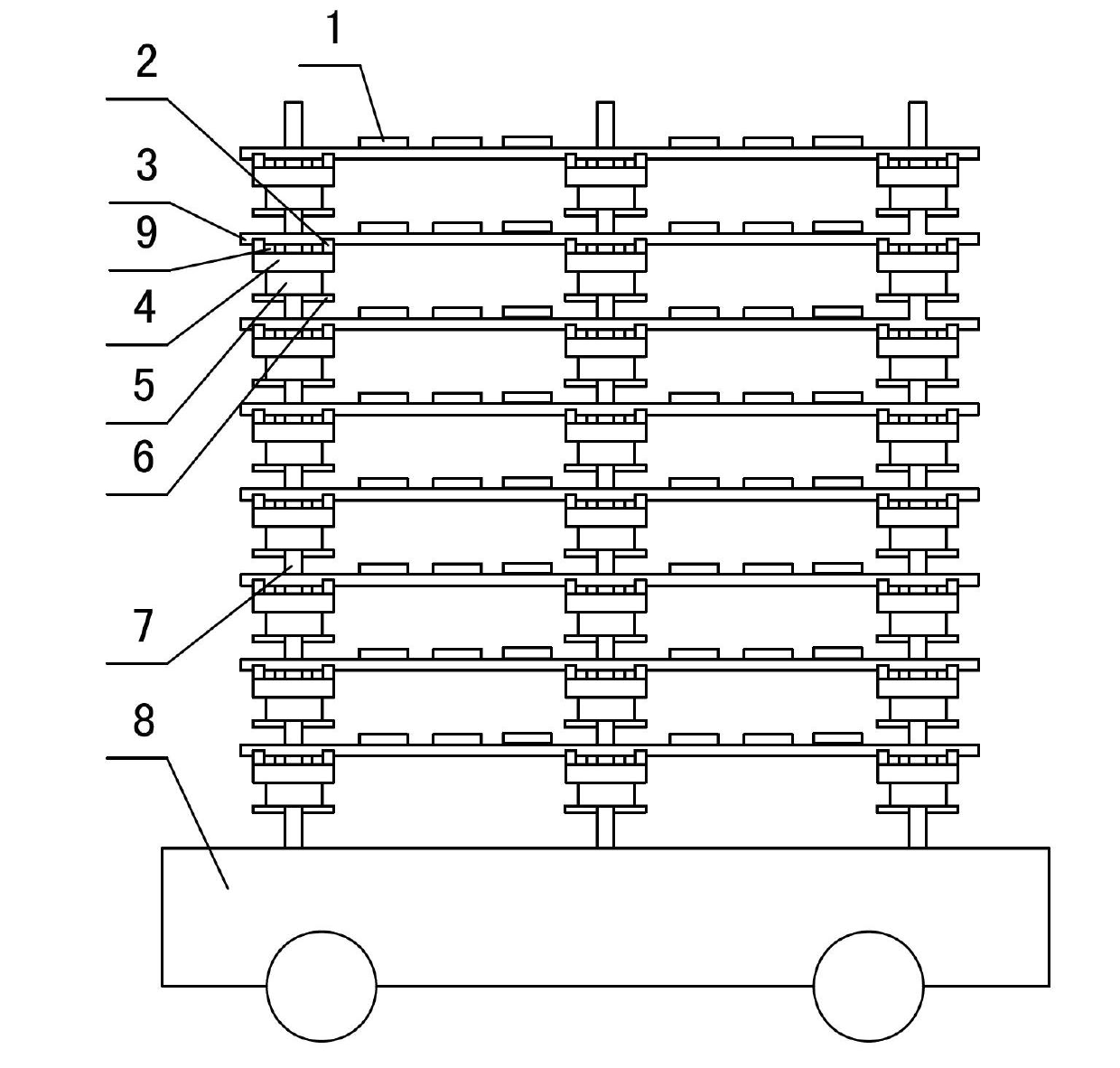
[0022] Such as image 3 , Figure 4 As shown, a change is made on the basis of Embodiment 1. The crossbeam 3 is arranged on the upper part of the support body 4 through the support rod 9, the support rod 9 is arranged between the stopper 2 and the column 7, and a layer of Beam 3. Others are the same as above.
[0023] When in use, similar to the use process of Embodiment 1, first determine the height of the porcelain, pull out the corresponding pin shaft 6 from the column 7, and then adjust the adjacent layer by moving the support body 4 or the adjustment sleeve 5 fitted on the column 7 The distance between the upper beam 3, and then the support bar 9 is placed between the block 2 and the column 7, and finally the beam 3 is placed on the support bar 9, and then the backing plate 1 is placed on the adjacent beam 3 on the same layer, that is You can start placing products.
[0024] Through the above embodiment, compared with the original technology, the firing time is shorte...
PUM
 Abstract
Description
Claims
Application Information
 - R&D Engineer
- R&D Manager
- IP Professional
- Industry Leading Data Capabilities
- Powerful AI technology
- Patent DNA Extraction
Browse by: Latest US Patents, China's latest patents, Technical Efficacy Thesaurus, Application Domain, Technology Topic, Popular Technical Reports.
© 2024 PatSnap. All rights reserved.Legal|Privacy policy|Modern Slavery Act Transparency Statement|Sitemap|About US| Contact US: help@patsnap.com