Hydraulic safety valve of antifreezing oil storage tank

A technology for oil storage tanks and safety valves, applied in safety valves, balance valves, valve devices, etc., can solve problems such as increased viscosity of sealing oil, freezing of flame arresters, storage tank accidents, etc.

Active Publication Date: 2012-08-15
PETROCHINA CO LTD
View PDF5 Cites 4 Cited by
  • Summary
  • Abstract
  • Description
  • Claims
  • Application Information

AI Technical Summary

Problems solved by technology

In a low temperature environment, the viscosity of the sealing oil increases, the fluidity decreases, and the operating pressure is much higher than the set value, resulting in failure of the hydraulic safety valve
The flame arrester is installed at the lower part of the hydraulic safety valve. Oil and water vapor enter the hydraulic safety valve after passing through the flame arrester. The flame arrester will also freeze in a low temperature environment, resulting in an accident in the storage tank.
[0005] At present, the winter in the area north of the Yangtze River is relatively long, and the longest area lasts for 5 months. In order to ensure the safety of the storage tank, the light-transmitting hole on the top of the storage tank has to be opened as an auxiliary breathing port, so there are the following points Disadvantages: 1. The light components on the top of the tank overflow the storage tank, which invisibly increases the loss of the production process and wastes resources; 2. Pollution to the atmosphere; 3. There is a fire hazard in the storage tank
4. Increased atmospheric corrosion of storage tanks

Method used


Image

  • Hydraulic safety valve of antifreezing oil storage tank
  • Hydraulic safety valve of antifreezing oil storage tank

Examples


Embodiment

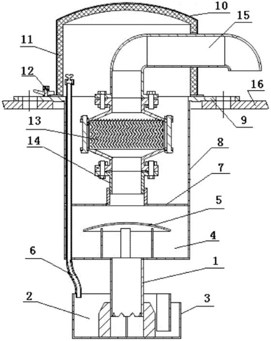
[0018] Embodiment: Taking a hydraulic safety valve of an antifreeze type petroleum storage tank with a total height of 1300mm, a diameter of 425mm, and an outer diameter of the mounting flange of 620mm as an example, further details will be given.

[0019] refer to figure 1 . Antifreeze hydraulic safety valve for petroleum storage tanks, mainly composed of central liquid conduit 1, liquid storage box 2, anti-shock plate 5, sealing liquid level detection device 6, cylinder body 8, mounting flange 9, windshield 10, flame arrester 13 , Connecting tube 14 and breathing tube 15 are formed.

[0020] The outer diameter of the mounting flange is 620mm, and a circular cylinder 8 is welded on the lower part of the center hole of the flat circular mounting flange 9. The inner diameter of the cylinder 8 is 415mm, the outer diameter is 425mm, and the height is 750mm. A 5 mm thick diaphragm 7 is welded in the cylinder body 8, and a fluid accumulation chamber 4 is formed between the diaphr...


PUM


Abstract

A hydraulic safety valve of an antifreezing oil storage tank is applied to pressure balance of the oil storage tank. A cylinder is welded at the lower of the center hole of an installation flange, a transverse diaphragm plate is welded in the cylinder, a fixing pipe is welded at the upper part of the transverse diaphragm plate, a flame arrester is connected at the top of the fixing pipe, and a breathing pipe is connected at the top of the fire arrester. A supporting rod and an impingement baffle are welded around the center hole of a bottom plate of the cylinder. A central hydraulic guide pipe is welded at the lower part of the center hole of the bottom plate of the cylinder, a metal plate and a liquid storage box are welded on the outer wall of the lower end of the central liquid guide pipe; and an arc-shaped steel plate is welded on the inner wall of the liquid storage box, and a clearance is left between the arc-shaped steel plate and the inner wall of the liquid storage box. a gapis arranged on the wall of the liquid storage box at the outer side of the arc-shaped steel plate. The hydraulic safety valve has the effects of changing the installation positions of the hydraulic safety valve and the fire arrester, sinking the hydraulic safety valve into the storage tank, and utilizing temperature of products in the storage tank to conduct insulation, and further being not frozen.

Description

technical field [0001] The invention relates to the technical field of petroleum storage tanks, in particular to a safety accessory for petroleum storage tanks, which is an antifreeze hydraulic safety valve for petroleum storage tanks, suitable for use in areas where the lowest temperature in winter is below zero. Background technique [0002] Steel vertical storage tanks are widely used in the petroleum and petrochemical industries as containers for storing finished or semi-finished oil products. Due to factors such as liquid level changes, day and night temperature differences, and sudden climate changes in the sending and receiving operations of oil storage tanks, the top of the storage tanks The space pressure changes. In order to prevent the interior of the oil storage tank from being ruptured due to high pressure or deflated due to low pressure, safety accessories to ensure the safe operation of the oil storage tank must be installed on the top of the oil storage tank....

Claims


Application Information

Patent Timeline
Patent Type & Authority Applications(China)
IPC IPC(8): F16K17/00B65D90/32
Inventor 王旭东丁建伍小三王为民陈东雷宇春黄立新王军
Owner PETROCHINA CO LTD
Why Eureka
Try Eureka