
Equipment for preparing fuel gas for gas turbine-steam turbine combined circulating power generation

A combined cycle power generation and steam turbine technology, which is applied in the direction of manufacturing combustible gas, combined combustion mitigation, and fuel pre-distillation, can solve the problems of high gas cost, stop, and failure to maintain the normal operation of gas turbines, etc., to achieve reasonable structure, Effects that are cheap to manufacture

Active Publication Date: 2012-08-15
孔令增 +1
View PDF3 Cites 7 Cited by
  • Summary
  • Abstract
  • Description
  • Claims
  • Application Information

AI Technical Summary

Problems solved by technology

However, the cost of gas prepared from these raw materials is extremely high, and the normal operation of the gas turbine cannot be maintained, resulting in the fact that the use of gas turbines to generate electricity is almost at a standstill
In order to reduce the cost of gas turbine power generation, those skilled in the art have adopted pressurized water gas, dry gas, etc. to supply gas turbines, but these methods still cannot meet the requirements of reducing the power generation cost of gas turbines

Method used


Image

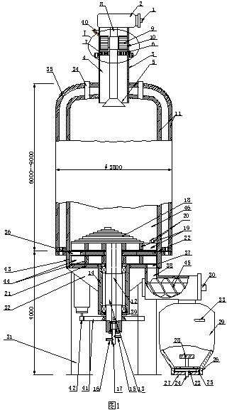
  • Equipment for preparing fuel gas for gas turbine-steam turbine combined circulating power generation
  • Equipment for preparing fuel gas for gas turbine-steam turbine combined circulating power generation
  • Equipment for preparing fuel gas for gas turbine-steam turbine combined circulating power generation

Examples


Embodiment Construction

[0008] The present invention will be further described with reference to the accompanying drawings.

[0009] A kind of equipment for preparing fuel gas for power generation according to the present invention comprises a furnace body 11, a roller extruder is installed on the upper end of the furnace body 11, and the roller extruder has a material receiving barrel 10, and the material receiving barrel 10 is sealed with the furnace body 11 connection, the first transmission shaft 8 is installed in the material receiving barrel 10, and two rollers 9 are installed on the first transmission shaft 8. The two rollers 9 are symmetrically distributed on both sides of the first transmission shaft 8, and the inner wall of the material receiving barrel 10 below the rollers 9 A circular steel disc 6 is installed on the top, and a through hole 7 is provided on the circular steel disc 6. The through hole 7 provided on the circular steel disc 6 is distributed on the track where the roller rotat...


PUM


Abstract

The invention provides equipment for preparing fuel gas for gas turbine-steam turbine combined circulating power generation, comprising a furnace body. An idler wheel extruder is installed at the upper end of the furnace body and is provided with a material receiving barrel, and the material receiving barrel is connected with the furnace body in an airtight mode. A transmission shaft is installed in the material receiving barrel, and two idler wheels are installed on the transmission shaft. A round steel disc is installed on the inner wall of the material receiving barrel below the idler wheels, and a through hole is arranged on the round steel disc. A feed port is arranged at the upper end of the material receiving barrel, the lower end of the material receiving barrel is an opening which is positioned in a fuel gas producer. A fire grate is installed at the lower end of the furnace body, and is connected with a second transmission shaft, and a slagging pipe is installed at one side of the bottom end of the furnace body. An air inlet is arranged in the second transmission shaft and is communicated with a gas mixing pipe, and the gas mixing pipe is respectively connected with a steam pipe and an air pipe. A power transmission piece is installed on the second transmission shaft and is connected with a motor. According to the invention, fuel gas prepared by adopting the equipment has high yield, high cleanliness and high calorific value, and the fuel gas is directly supplied for gas turbine-steam turbine combined circulating power generation.

Description

technical field [0001] The invention relates to a device for preparing gas, which is a device for preparing gas for gas turbine-steam turbine combined cycle power generation. Background technique [0002] The gas used for power generation by gas turbines requires technical indicators such as high calorific value and high purity, otherwise, the gas turbines cannot continue to operate normally. To make the gas meet the above technical indicators, the fuel used for preparing the gas must be refined lump coal, coke or high-quality fuel oil. However, the cost of gas prepared from these raw materials is extremely high, and the normal operation of the gas turbine cannot be maintained, resulting in the almost cessation of power generation by the gas turbine. In order to reduce the cost of gas turbine power generation, those skilled in the art have used pressurized water gas, dry gas, etc. to supply the gas turbine, but these methods still cannot meet the requirements of reducing t...

Claims


Application Information

Patent Timeline
IPC IPC(8): C10J3/20C10J3/30C10J3/42C10J3/58
CPCY02E20/16C10L2290/24Y02E50/30C10L5/04C10L2290/28C10L5/363C10L5/08B01J2/20Y02E50/10B30B11/228
Inventor 孔令增
Owner 孔令增
Learn More