
Series-parallel tilting drive mechanism of tilt rotor aircraft

A technology of tilting rotor and driving mechanism, which is applied in the field of hybrid tilting driving mechanism, can solve the problems of unfavorable rotor downwash airflow, poor lateral stability of aircraft, weakening propeller lift, etc. significant effect

Inactive Publication Date: 2012-08-15
YANGZHOU UNIV
View PDF3 Cites 7 Cited by
  • Summary
  • Abstract
  • Description
  • Claims
  • Application Information

AI Technical Summary

Problems solved by technology

[0003] The American V22 "Osprey" has the following disadvantages: 1) The wing stiffness is weak, and it is easy to flutter. , it is easy to cause flutter, which limits the further improvement of flight speed; 2) the lateral stability is relatively poor. In the flight state, the lateral stability is relatively poor; 3) The lift force is greatly weakened. In order to ensure sufficient lift force in level flight, the area of ​​the V22 wing must be large enough, but in order to avoid the weak stiffness caused by the too long cantilever under the force of the wing, the V22 The wings can only be thick and short. During the take-off phase, the rotor downwash airflow is seriously blocked by the wings, which greatly weakens the propeller lift.
The tilt-wing helicopter with the application number 201010599982.2 uses a parallel mechanism to construct the tilt-rotor drive mechanism, which can improve the aeroelastic stability of the aircraft by increasing the stiffness of the wing. However, since the parallel mechanism is installed on the wing, the parallel mechanism directly drives of the rotor relative to the wing X The direction (the direction the aircraft is heading) cannot be flexibly arranged according to aerodynamics, which is not conducive to further reducing the influence of rotor downwash on lift

Method used


Image

  • Series-parallel tilting drive mechanism of tilt rotor aircraft
  • Series-parallel tilting drive mechanism of tilt rotor aircraft
  • Series-parallel tilting drive mechanism of tilt rotor aircraft

Examples


Embodiment Construction

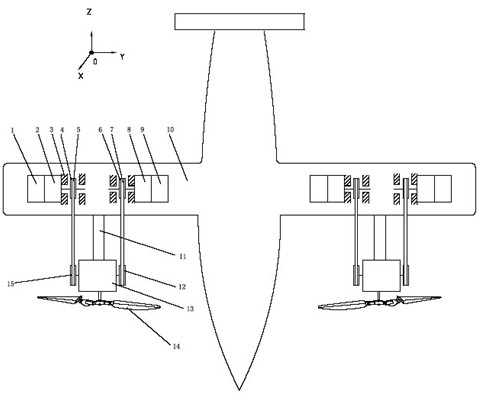
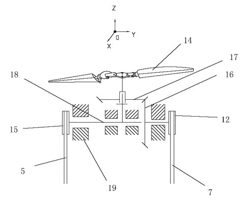
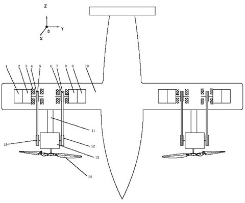
[0018] Such as figure 1 , figure 2 As shown, the hybrid tilting drive mechanism is composed of a swing engine 1, a middle swing pulley 4, a swing transmission belt 5, a rotation engine 9, a wing rotation pulley 6, a rotation transmission belt 7, and a two-degree-of-freedom rotation mechanism 13. Two-degree-of-freedom rotating mechanism 13 is provided with frame 19, tie rod 18, center wheel 16, planetary gear 17, rotor swing belt pulley 15, rotor rotation belt pulley 12, and frame 19 is fixed on the wing 10 by support bar 11, The center wheel 16 and the tie rod 18 are installed on the frame 19, the tie rod 18 supports the planetary gear 17, the center wheel 16 and the planetary gear 17 mesh to form a gear pair, the rotor 14 is installed on the planetary wheel 17, the tie rod 18 and the rotor swing belt Wheel 15 is fixedly connected, and center wheel 16 is fixedly connected with rotor rotating belt pulley 12. The swing engine 1 and the middle swing pulley 4 are installed on t...


PUM


Abstract

The invention discloses a series-parallel tilting drive mechanism of a tilt rotor aircraft, belonging to the technical field of helicopter manufacturing. The series-parallel tilting drive mechanism of the tilt rotor aircraft is formed by installing and connecting a swing engine, middle swing belt wheels, swing driving belts, a rotary engine, wing rotary belt wheels, rotary driving belts and a two-degree-of-freedom turning mechanism. The hybrid tilting drive mechanism is scientific and rational in structural design and capable of being applied to the tilt rotor aircrafts; the tilt rotor aircraft has vertical / short-distance taking-off and landing capacity; the tilt rotor aircraft has the advantages of low oil consumption, high speed, large air range, high load and the like, and the transportation cost of the tilt rotor aircraft is only half of that of helicopters.

Description

technical field [0001] The invention relates to a hybrid tilting drive mechanism of a tilting rotor aircraft, which belongs to the technical field of helicopter manufacturing. Background technique [0002] The more successful tiltrotor aircraft is the American V22 "Osprey". It installs the engine and rotor for tilting motion at the wing tip, and adjusts the flight state of the aircraft by tilting the rotor. When the axis of the propeller is horizontal, it will Give the aircraft a forward pull; when the propeller axis is vertical, it provides an upward lift to the aircraft. [0003] The American V22 "Osprey" has the following disadvantages: 1) The wing stiffness is weak, and it is easy to flutter. , it is easy to cause flutter, which limits the further improvement of flight speed; 2) the lateral stability is relatively poor. In the flight state, the lateral stability is relatively poor; 3) The lift force is greatly weakened. In order to ensure sufficient lift force in level...

Claims


Application Information

Patent Timeline
IPC IPC(8): B64C27/12B64C27/08
Inventor 姜铭朱望东孙钊李鹭扬
Owner YANGZHOU UNIV
Learn More