Eureka AIR delivers breakthrough ideas for toughest innovation challenges, trusted by R&D personnel around the world.

Real-time control device and real-time control method for motion direction of electromagnetic energy-regeneration semi-active suspension

A technology of semi-active suspension and movement direction, which is applied in the direction of electromechanical devices, suspensions, elastic suspensions, etc., which can solve the problems of low vehicle safety performance and inability to limit the movement direction of the suspension, so as to improve driving safety, Reduce the effect of pitch and roll

Inactive Publication Date: 2012-08-08
JIANGSU UNIV
View PDF4 Cites 52 Cited by
  • Summary
  • Abstract
  • Description
  • Claims
  • Application Information

AI Technical Summary

Problems solved by technology

The defect of this electromagnetic energy-feeding semi-active suspension is that it cannot limit the movement direction of the suspension in real time when the vehicle is subjected to a large inertial force, resulting in low driving safety performance of the vehicle.

Method used


Image

  • Real-time control device and real-time control method for motion direction of electromagnetic energy-regeneration semi-active suspension
  • Real-time control device and real-time control method for motion direction of electromagnetic energy-regeneration semi-active suspension
  • Real-time control device and real-time control method for motion direction of electromagnetic energy-regeneration semi-active suspension

Examples


Embodiment Construction

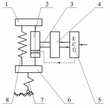
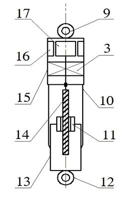
[0012] Such as figure 1 As shown, the electromagnetic energy-feeding semi-active suspension and its control system used in the present invention are; in the vertical direction (the direction of all physical quantities related to the suspension movement is in the vertical direction), the wheel mass 6 and tire equivalent spring 7 form a wheel, the wheel is located below the sprung mass 1, the suspension spring 8 and the electromagnetic feed damping force generator 2 are connected in parallel between the wheel and the sprung mass 1, the wheel directly interacts with the ground and Make the suspension vibrate. The electromagnetic energy-feeding damping force generator 2 is equipped with a two-way controllable double ratchet mechanism 3 that is both real-time controllable in both directions; The two current feedback wires are connected to the energy-feeding control circuit 4, and the energy-feeding control circuit 4 is connected to the control unit 5 with multiple control lines an...


PUM


Abstract

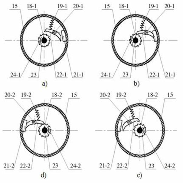
The invention discloses a real-time control device and a real-time control method for a motion direction of an electromagnetic energy-regeneration semi-active suspension of a vehicle. A bi-directional controllable double ratchet mechanism composed of a first ratchet mechanism and a second ratchet mechanism which are jointly arranged on an input shaft of an energy-regeneration motor rotor is arranged between an energy-regeneration motor and a nut-ball screw mechanism. The first ratchet mechanism and the second ratchet mechanism respectively comprise a ratchet, a pawl, a pawl rotating shaft, a tensioning spring and an electromagnet. The electromagnets are electrically connected with a control unit, and the rotating directions of the two ratchets combined with the pawls are opposite. When the control unit inputs control signals to a first electromagnet and a second electromagnet of the first ratchet mechanism and the second ratchet mechanism, the input shaft of the energy-regeneration motor rotor can only rotate anticlockwise or clockwise, and the suspension can only be stretched or compressed. When the control unit does not input control signals to the first electromagnet or the second electromagnet, the suspension can only be stretched and compressed. When the vehicle is subjected to a large inertial force, by real-time control of the motion direction of the related suspension, pitching and side tipping of the vehicle are reduced, and the running safety of the vehicle is improved.

Description

technical field [0001] The invention belongs to the technical field of vehicle suspension structure and control, and in particular relates to a control device and method for an electromagnetic energy-feeding semi-active suspension of a vehicle. Background technique [0002] Suspension is an important structural and functional part of the vehicle, which has a great influence on the overall performance of the vehicle. Vehicle suspension can be divided into passive suspension, semi-active suspension and active suspension according to its working principle. Passive suspension is mainly composed of springs, shock absorbers, etc. The shock absorber consumes and the spring buffers the vibration energy between the vehicle axle and the body mass to obtain the vibration reduction effect, but the fixed stiffness and damping are difficult to meet various vibration reduction requirements . Ordinary semi-active suspension is to transform the shock absorber with constant damping value of...

Claims


Application Information

Patent Timeline
IPC IPC(8): B60G17/016H02K7/116F16F15/03
Inventor 陈士安王勇刚何仁王胜武晓晖
Owner JIANGSU UNIV
Why Eureka
Eureka Blog
Learn More