
Control circuit of waterproof LED (Light Emitting Diode) flashlight

A technology of LED flashlight and control circuit, which is applied in the direction of electric lamp circuit layout, electric light source, lighting device, etc., which can solve the problems of damage, large standby power consumption, and few dimming gears, etc., and achieve the effect of prolonging the service life

Inactive Publication Date: 2012-08-01
WUXI VDSON ELECTRONICS
View PDF4 Cites 4 Cited by
  • Summary
  • Abstract
  • Description
  • Claims
  • Application Information

AI Technical Summary

Problems solved by technology

[0002] At present, ordinary LED flashlights consume a lot of power in standby, have few dimming gears, and the switch is mechanical, which is easy to be poorly connected and damaged. This circuit is designed to overcome these shortcomings.

Method used


Image

  • Control circuit of waterproof LED (Light Emitting Diode) flashlight
  • Control circuit of waterproof LED (Light Emitting Diode) flashlight
  • Control circuit of waterproof LED (Light Emitting Diode) flashlight

Examples


Embodiment Construction

[0018] In order to make the technical means, creative features, objectives and effects achieved by the present invention easy to understand, the present invention will be further described below in conjunction with specific illustrations.

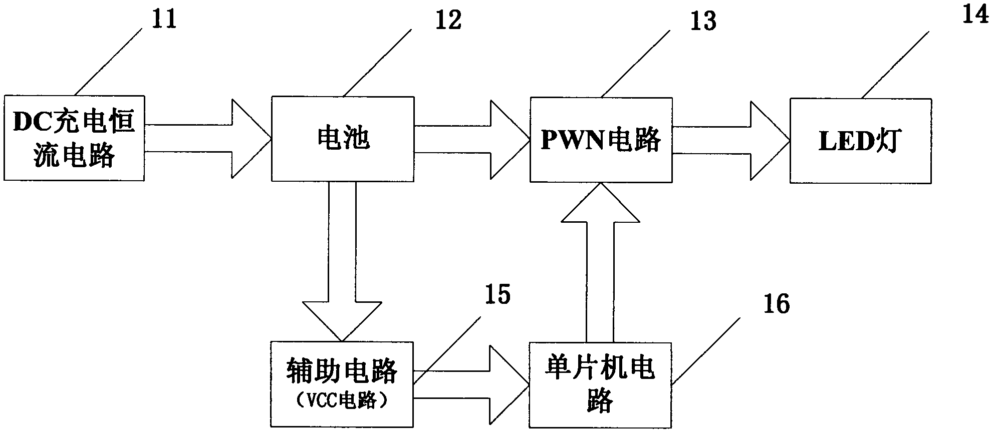
[0019] Such as figure 1 As shown, the waterproof LED flashlight control circuit of the present invention is composed of a DC charging constant current circuit 11, a battery 12, a PWN circuit 13, a single-chip microcomputer circuit 16, an auxiliary circuit 15 and an LED lamp 14.

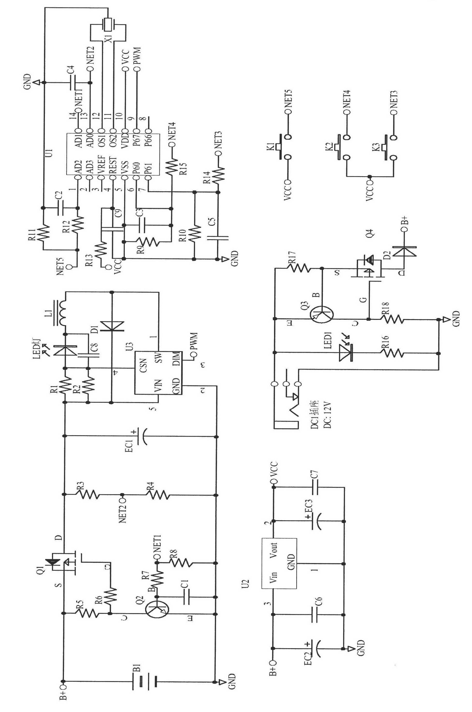
[0020] Such as figure 2 As shown, the circuit is provided with a power supply B1, resistors R5 and R6 connected to the power supply B1, an insulated gate field effect transistor Q1, a transistor Q2, resistors R3 and R4, a capacitor EC1, and a step-down constant current source U3; the transistor Q2 is also Capacitor C1, resistors R7 and R8 are connected; step-down constant current source U3 is also connected to resistors R1 and R2, capacitor C8, diode D1, inductor...


PUM


Abstract

The invention discloses an illumination control circuit of a novel LED (Light Emitting Diode) flashlight. The circuit is composed of a DC (Direct Current) charging constant-current circuit, batteries, a PWM (Pulse Width Modulation) circuit, a singlechip microcomputer circuit, an auxiliary circuit and an LED lamp. The entire circuit is powered by adopting six 1.2V nickel-metal hydride batteries, has the capacity of 700mAh and is divided into five gears in total, and two touch keys are adopted to increase or reduce the brightness of the lamp. The work current is 700mA when the maximal gear is supported, the work current at the minimal gear corresponds to the longest discharge time, and the brightness can be selected as required. After the control circuit is started, the work current of the lamp is set to be the middle gear, the current is 350mA, and the brightness is about 50%. When the voltage of the batteries is reduced to 6V, the power supply is cut off, the quiescent current of the circuit is smaller than 50 mu A, a switch is used for tuning on and turning off the lamp by adopting a magnetic element (a magnetic reed pipe), and thus, the LED flashlight is prolonged in service life.

Description

Technical field: [0001] The invention relates to an LED torch, in particular to a novel LED torch lighting control circuit. Background technique: [0002] At present, the ordinary LED flashlight consumes a lot of power in standby, has few dimming gears, and the switch is mechanical, which is easy to be poorly connected and damaged. This circuit is designed to overcome these shortcomings. Invention content: [0003] In view of the above technical problems, the present invention provides a novel LED flashlight lighting control circuit. The control circuit adjusts the LED lamp by setting the dimming gear from 70mA to 700mA. And the reed switch is used to control the on and off of the light when the battery voltage drops to 6V and the quiescent current of the circuit is less than 50uA, so as to prolong the service life of the LED flashlight. [0004] Concrete technical scheme of the present invention is as follows: [0005] The waterproof LED flashlight control circuit is c...

Claims


Application Information

Patent Timeline
Patent Type & Authority Applications(China)
IPC IPC(8): H05B37/02
Inventor 刘素民
Owner WUXI VDSON ELECTRONICS
Learn More