
Parallel experimental device for six-degree-of-freedom gait simulation

An experimental device and a technology of degrees of freedom, applied in the field of mechanical devices, can solve problems such as inability to form a dual relationship, few degrees of freedom, and mismatch between active and passive relationships, and achieve the effect of simple and compact structure and high rigidity

Inactive Publication Date: 2012-08-01
SHANGHAI JIAO TONG UNIV
View PDF4 Cites 24 Cited by
  • Summary
  • Abstract
  • Description
  • Claims
  • Application Information

AI Technical Summary

Problems solved by technology

[0003] Through the retrieval of the prior art, it is found that although the previous ankle gait simulation test bench can simulate the main motion of the ankle and the measurement and control of the loading of the ankle and the vertical ground reaction force, it has the following disadvantages: it cannot fully simulate and Controlling the 6 degrees of freedom movement of the tibia is often a movement with few degrees of freedom, so there is a certain gap between the movement situation of the real gait
Recently, the gait dynamics simulator developed by the University of Washington realizes the 6-DOF movement of the ankle joint of the lower limbs, but uses the 6-DOF movement of the ground (force plate) to relatively simulate the foot gait movement. Although this simulator achieves 6 degrees of freedom in motion, it actually does not match the active and passive relationship of real gait movement, and cannot form a dynamic dual relationship.
In addition, the existing six-degree-of-freedom gait simulator takes more than 2 seconds to simulate a gait, which takes more time than a real gait, so there is a gap between the simulated speed and the real gait

Method used


Image

  • Parallel experimental device for six-degree-of-freedom gait simulation
  • Parallel experimental device for six-degree-of-freedom gait simulation
  • Parallel experimental device for six-degree-of-freedom gait simulation

Examples


Embodiment

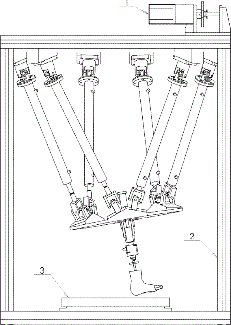
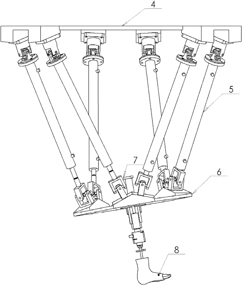
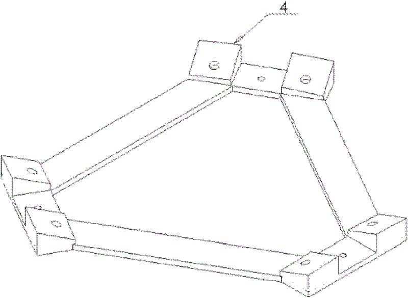
[0033] Such as figure 1 As shown, the parallel six-degree-of-freedom gait simulation experimental device includes a frame structure 1, figure 2 The six-bar parallel mechanism and Figure 8 tandem loading mechanism. Among them, the frame 1 is fixed on the ground, the tendon driving motor 2 is installed on the top of the frame, the six-bar parallel mechanism is suspended on the upper part of the frame, and the height-adjustable force plate 3 is installed on the lower part of the frame. The six-bar parallel mechanism is fixed to the frame 1 through its fixed platform 4, and the series loading mechanism is installed on the moving platform 6 of the six-bar parallel mechanism.

[0034] Such as figure 2 As shown, the six-bar parallel mechanism adopts a typical Stewart parallel structure, which is composed of a fixed platform 4, 6 top U-shaped fixed seats 16, 6 identical motion branch chains 5, 6 bottom U-shaped seats and a moving platform 6 UPU parallel mechanism, its moving pl...


PUM


Abstract

The invention relates to a parallel experimental device for six-degree-of-freedom gait simulation, which comprises a frame, a six-bar parallel mechanism and a series loading device, wherein the frame is provided with a force-plate-mounting-height adjusting device and a tendon driving device. The force-plate-mounting-height adjusting device is mounted on a lower platform surface of the frame and comprises four lead screws, four lower nuts, four upper nuts and two force plate mounting racks, the tendon driving device comprises a motor, a coupler, a reduction gear set, a sprocket and a chain, the six-bar parallel mechanism comprises a fixed platform, a movable platform, 12 groups of hooke hinges and six identical movement branching chains, and the series loading device comprises a hydraulic cylinder, a guide rail fixing shaft, a force sensor and a shin bone connecting shaft system with an indexing disc, wherein the hydraulic cylinder is fixed onto a movable platform, and the guide rail fixing shaft is capable of sliding along a sliding groove. The experimental device can not only simulate six-degree-of-freedom movement of shin bones fixed by a loading shaft system, but also axially load force (such as gravity, microgravity or the like) to the shin bones, and can be effectively used for researching ankle dynamics.

Description

technical field [0001] The invention relates to a mechanical device in the technical field of motion simulation, in particular to an experimental device with 6 degrees of freedom for gait motion simulation and foot loading. Background technique [0002] The human foot is an important weight-bearing and locomotion organ, with 26 bones, 33 joints and more than 100 tendons, ligaments and muscles. The gait simulation experimental device developed in recent years is an experimental device that uses cadaver feet to simulate the movement of human legs or single legs. Relying on this device, researchers can investigate the dynamic characteristics of the human foot-ankle system, verify the correctness of the foot-ankle model, the effectiveness of the protective gear design and other biomechanical issues, and explore the cause of the foot in clinical medicine, and can obtain medical rehabilitation. Invaluable data for research and armor design. [0003] Through the retrieval of the ...

Claims


Application Information

Patent Timeline
IPC IPC(8): G09B23/28
Inventor 王尚城王冬梅施光林
Owner SHANGHAI JIAO TONG UNIV
Learn More