Eureka AIR delivers breakthrough ideas for toughest innovation challenges, trusted by R&D personnel around the world.

Light guide plate and light source module

A light source module, light guide plate technology, applied in electric light sources, light guides, optics, etc., can solve problems such as brightness reduction and light loss, and achieve the effects of reducing light loss, reducing costs, and high light utilization.

Active Publication Date: 2012-08-01
CORETRONIC
View PDF15 Cites 12 Cited by
  • Summary
  • Abstract
  • Description
  • Claims
  • Application Information

AI Technical Summary

Problems solved by technology

However, when the light beam passes through more than one prism sheet and the light beam is fully reflected back to the light guide plate, light loss will be caused, thus reducing the brightness provided by the light source module

Method used


Image

  • Light guide plate and light source module
  • Light guide plate and light source module
  • Light guide plate and light source module

Examples


Embodiment Construction

[0086] The aforementioned and other technical contents, features and effects of the present invention will be clearly presented in the following detailed description of a preferred embodiment with reference to the drawings. The directional terms mentioned in the following embodiments, such as: up, down, left, right, front or back, etc., are only directions referring to the attached drawings. Accordingly, the directional terms are used to illustrate and not to limit the invention.

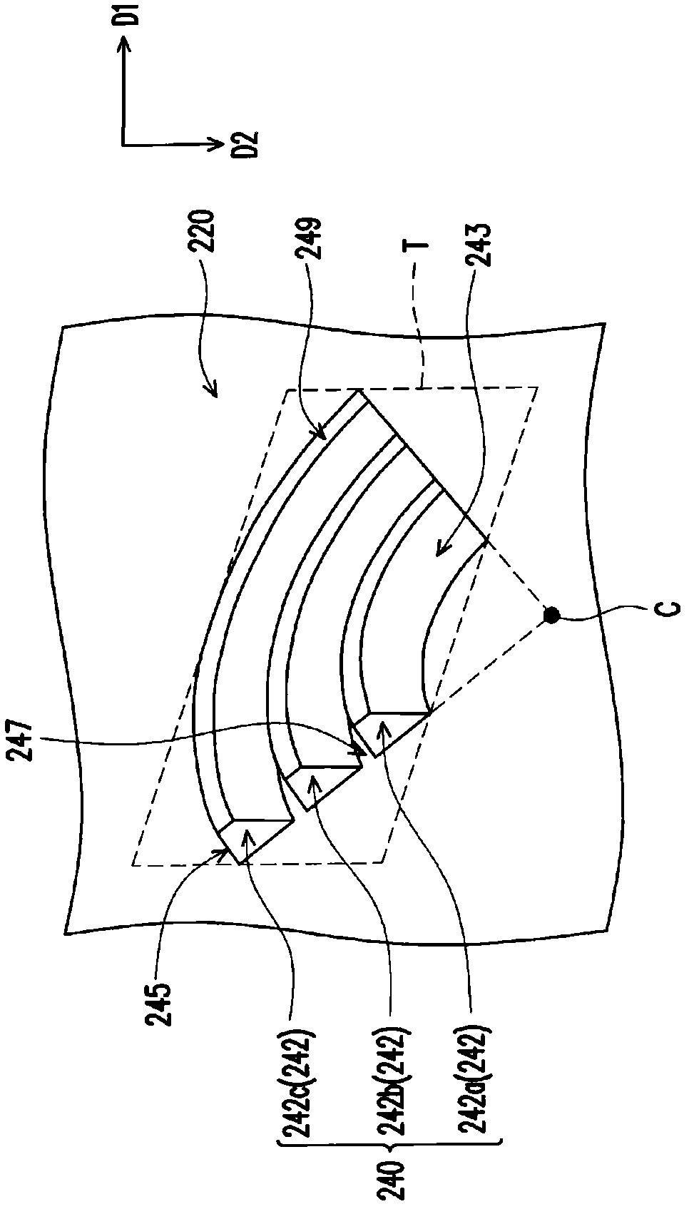
[0087] Figure 1A is a schematic cross-sectional view of a light source module according to an embodiment of the present invention, Figure 1B for Figure 1A The three-dimensional schematic diagram of the light guide plate and light-emitting elements in , and Figure 1C for Figure 1A A partial enlargement of the second surface in . Please refer to Figure 1A to Figure 1C , the light source module 100 of this embodiment includes a light guide plate 200 and at least one light emitting element 110 ...


PUM

PropertyMeasurementUnit
angleaaaaaaaaaa
angleaaaaaaaaaa
angleaaaaaaaaaa

Abstract

A light guide plate including a first surface, a second surface, at least one light incident surface, and a plurality of groove sets is provided. The light incident surface connects the first surface and the second surface. The groove sets are separately disposed on the second surface. Each of the groove sets includes a plurality of curved grooves. Each of the curved grooves has a curved inclined reflective surface and a curved back-to-light surface connected thereto. The curved inclined reflective surface is inclined with respect to the first surface. The curved grooves of each of the groove sets curve toward the same curving direction. The curved inclined reflective surface of one of two adjacent curved grooves is connected to the curved back-to-light surface of the other one of the two adjacent curved grooves through a connection surface. A light source module is also provided. By using the light guide plate, the light loss can be reduced. The light source module provided in the invention has higher light utilization rate.

Description

【Technical field】 [0001] The invention relates to an optical element and a light source, and in particular to a light guide plate and a light source module. 【Background technique】 [0002] In the existing side light source module, the light guide plate is used to guide the light beam emitted by the light-emitting element disposed beside the light guide plate to the front of the light guide plate to form a surface light source. Generally speaking, when the light beam emitted by the light-emitting element enters the light guide plate through the side of the light guide plate, it will be continuously totally reflected by the upper and lower surfaces of the light guide plate, and be confined in the light guide plate. However, the microstructures on the surface of the light guide plate can destroy the total reflection, so that the light beam enters the upper surface at an angle smaller than the critical angle and penetrates the upper surface. [0003] Although the microstructure...

Claims


Application Information

Patent Timeline
Patent Type & Authority Applications(China)
IPC IPC(8): G02B6/00G02F1/13357F21S10/06F21V8/00
CPCG02B6/0043G02B6/0038G02B6/0036G02B6/0061
Inventor 松本伸吾蔡汉文游志杰梁宏维
Owner CORETRONIC
Why Eureka
Eureka Blog
Learn More