
Synthetic aperture radiometer visibility phase error correction method based on array rotation

A comprehensive aperture and phase error technology, applied to radio wave measurement systems, instruments, etc., can solve problems such as limiting system performance, increasing system weight, volume phase instability, etc.

Active Publication Date: 2012-08-01
HUAZHONG UNIV OF SCI & TECH
View PDF2 Cites 19 Cited by
  • Summary
  • Abstract
  • Description
  • Claims
  • Application Information

AI Technical Summary

Problems solved by technology

But this advantage is at the cost of signal processing complexity, especially for phase error correction of spaceborne synthetic aperture system: internal noise injection will greatly increase the weight, volume and phase instability of the system, these factors limit further improved system performance

Method used


Image

  • Synthetic aperture radiometer visibility phase error correction method based on array rotation
  • Synthetic aperture radiometer visibility phase error correction method based on array rotation
  • Synthetic aperture radiometer visibility phase error correction method based on array rotation

Examples


Embodiment Construction

[0017] The present invention will be described in further detail below in conjunction with the accompanying drawings.

[0018] The invention utilizes the relationship among the measured visibility, the ideal visibility, and the phase error of the array element to solve the phase error of the array element by simultaneously establishing a set of linear equations, and then corrects the measured visibility.

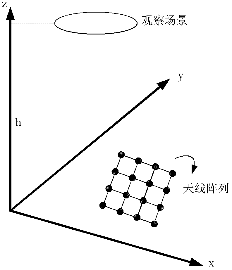
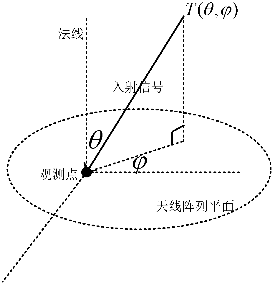
[0019] The schematic diagram of the calibration method is as figure 1 As shown, the antenna array is located in the x, y plane, and the array can be rotated around the center of the array in this plane. The observation scene is located in the z=h plane parallel to the antenna array, h is much larger than the size of the array, and the far-field condition is satisfied.

[0020] The steps of the present invention are as follows:

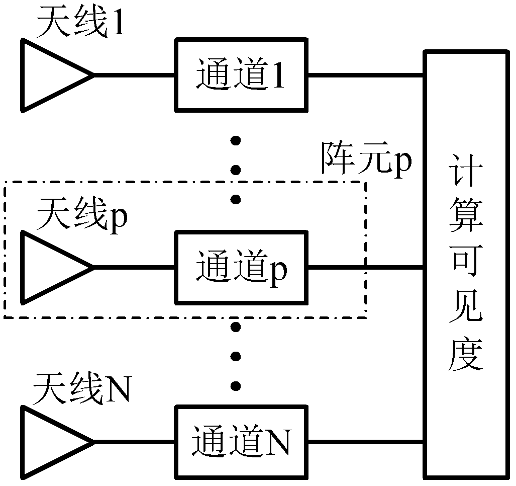
[0021] For an N-element synthetic aperture radiometer, using each antenna a p Receive the microwave thermal radiation signal of the scene under t...


PUM


Abstract

The invention provides a synthetic aperture radiometer visibility phase error correction method based on array rotation. The method comprises the following steps of: rotating an antenna array by 180 DEG so that radiation signals of a tested scene are respectively received by the antenna array before and after rotation; establishing an equation set by using the characteristic that the antenna array element phase error does not change along with array rotation, simultaneously solving the equation set to obtain the antenna array element phase error, and further correcting the visibility according to the antenna array element phase error. The method does not rely on additional internal noise injection networks and external auxiliary sources, the array element phase error of synthetic apertureradiometer visibility can be corrected by using the observation scene per se, and the complexity of the traditional synthetic aperture radiometer correction system is effectively reduced.

Description

technical field [0001] The invention relates to the technical field of microwave remote sensing and detection, in particular to a visibility phase error correction method of a synthetic aperture radiometer. Background technique [0002] The synthetic aperture radiometer uses multiple discrete small antennas to synthesize a larger real aperture, which is arranged in a sparse array, which greatly reduces the mass and volume of the antenna, and solves the inherent contradiction between resolution and aperture size. But this advantage is at the cost of signal processing complexity, especially for phase error correction of spaceborne synthetic aperture system: internal noise injection will greatly increase the weight, volume and phase instability of the system, these factors limit further improved the system performance. Contents of the invention [0003] The purpose of the present invention is to provide a method for correcting the visibility phase error of the synthetic aper...

Claims


Application Information

Patent Timeline
IPC IPC(8): G01S7/40
Inventor 李青侠靳榕沈尚宇陈柯
Owner HUAZHONG UNIV OF SCI & TECH
Learn More