
Regulation structure of swing arm and swing center for controlling stroke of sewing machine

A technology for controlling the stroke and adjusting the structure, which is applied to sewing machine components, cloth pressing mechanisms, sewing equipment, etc., can solve the problems of inability to meet, the structure cannot be adjusted, and the stroke of the cloth pressing foot is uncertain, and achieves simplified, convenient and fast assembly. Effect

Inactive Publication Date: 2012-08-01
曾贤长
View PDF3 Cites 0 Cited by
  • Summary
  • Abstract
  • Description
  • Claims
  • Application Information

AI Technical Summary

Problems solved by technology

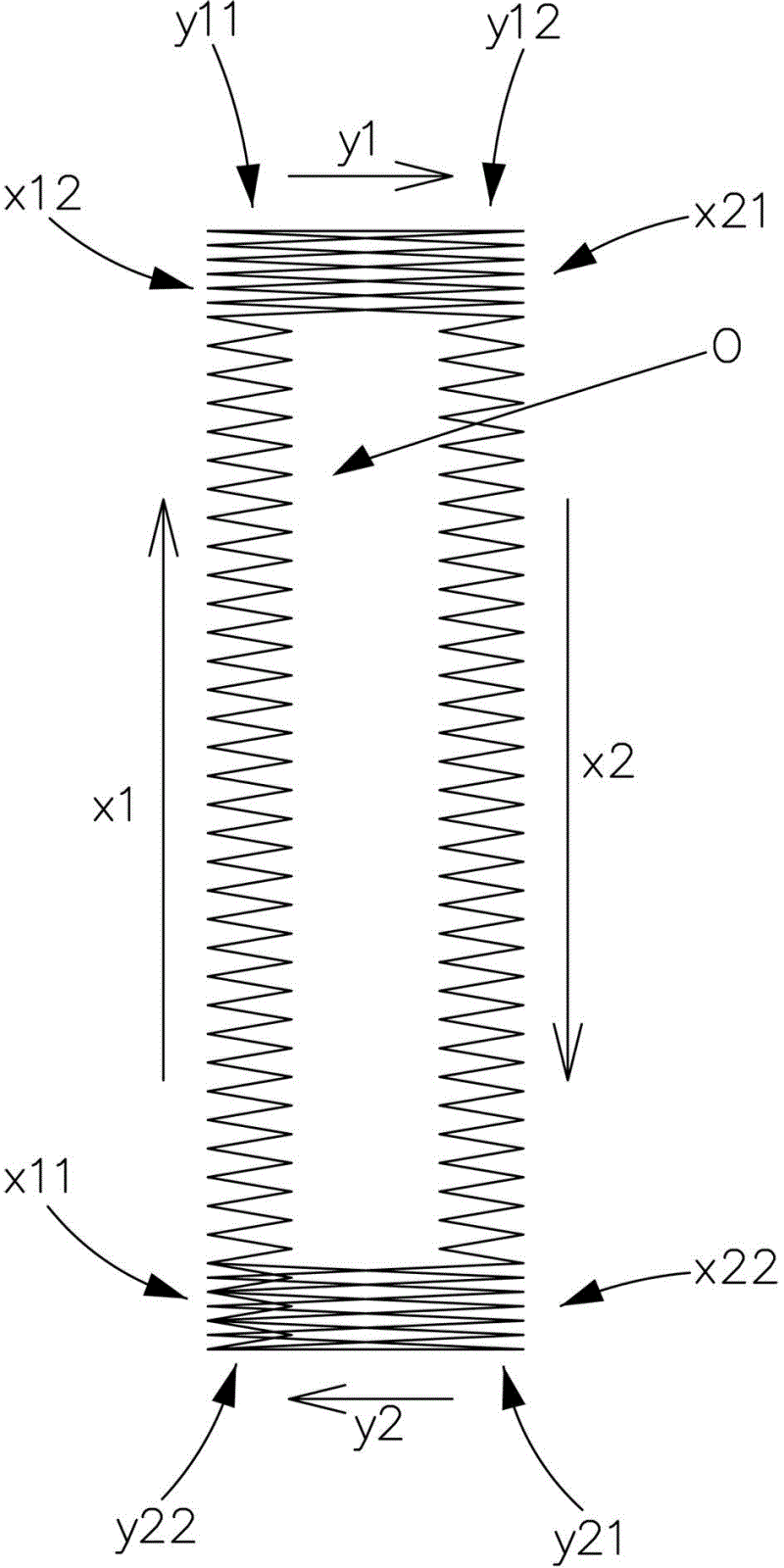
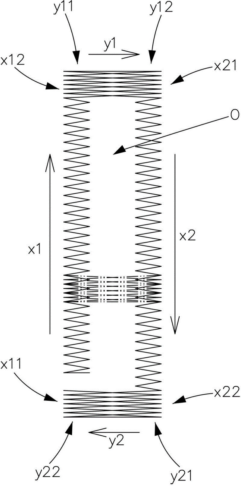
[0003] It is only reasonable that the aforementioned actions should be able to be completed smoothly under ideal conditions. However, in the current sewing machine, the structure of this part cannot be adjusted. After the sewing machine is used for a period of time, the parts may loosen and the error margin may increase. Therefore, the positions where the first and second sensing electrodes of the stroke sensing devices are respectively touched and electrically connected are often different from the correct position of the presser foot, and the shape of the buttonhole O thus sewn will be different. There are missing, such as Picture 1-1 As shown, when passing through the third stroke X2 to the end point X22 of the stroke, because the first and second sensing electrodes are respectively touched by the electrically conductive position and the correct position of the presser foot, the buttonhole O The lengths of the long sides of the two sides are different, so that the buttonhole O cannot be completely formed;
[0004] And there is also an industry that sets the contact position of the first and second sensing electrodes of the stroke sensing device and the relative position of the presser foot in a form that can adjust the displacement of each other, so that the position of the starting point of the stroke of the presser foot can be adjusted. Control, but its adjustment structure design uses the cam shape as the benchmark for adjusting displacement during adjustment. In the principle of mechanical design, it is known that when the cam is used for displacement adjustment, there will often be a displacement change in a non-unidirectional direction, that is, during the adjustment process, when To adjust the movement in the horizontal direction, it is often accompanied by displacement in the vertical direction, resulting in unnecessary side effects of movement in the other direction, which makes the stroke of the presser foot quite uncertain, so it cannot meet the current requirements. There is a need for accurate control of the stroke of the presser foot, so there is a need for improvement

Method used


Image

  • Regulation structure of swing arm and swing center for controlling stroke of sewing machine
  • Regulation structure of swing arm and swing center for controlling stroke of sewing machine
  • Regulation structure of swing arm and swing center for controlling stroke of sewing machine

Examples


Embodiment Construction

[0055] For the present invention to achieve the above-mentioned purpose, the technology, means and other effects adopted, hereby give a preferred feasible embodiment and cooperate with the drawings in detail as follows, believe that the above-mentioned purpose of the present invention, features and other advantages, should be obtained by it For an in-depth and specific understanding, the present invention is not the only embodiment, so please describe it here.

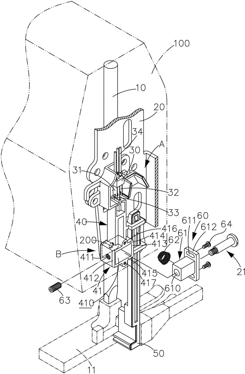
[0056] The structure of the present invention is shown in Fig. 2- Figure 5 As shown, a fixed frame 20 bent from a plate-shaped structure is provided at the free end of the sewing machine cantilever 100 near the presser foot rod 10, and a stroke sensing device A is provided on the fixed frame 20. The stroke sensing device A It includes a sensor 30, a swing arm group B that changes its position with the movement of the presser foot 11 provided at the bottom of the presser foot bar 10, and the swing arm group B has a sen...


PUM


Abstract

The invention provides a regulation structure of a swing arm and a swing center for controlling stroke of a sewing machine, which is particularly suitable for cloth presser foot stroke control of a computer sewing machine. Aiming at the swing center arranged at the position of a pivot on a middle section of the swing arm of a stroke sensing device for changing the cloth presser foot, the regulation structure is provided with a regulation device and a relative structure matched with the regulation device, a sliding block and a sliding groove which can horizontally slide with each other are arranged at the position of the pivot of the swing center of the swing arm and the relative regulation device, and a regulation bolt and an elastic assembly are arranged between the sliding block and thesliding groove. By means of length change of the regulation bolt extending towards a position between the sliding block and the sliding groove and pre-stress of the elastic assembly butting against the position between the sliding groove and the sliding block at the normal state, a swing center point during pivoting of the swing arm and a relative position of a swing arm overall structure can be accurately and conveniently changed in the horizontal direction so as to enable the swing arm to be regulated to an electrical connection position of the cloth presser foot at a stroke starting point,and the purpose that the position of the stroke sensing device can be regulated accurately is achieved.

Description

technical field [0001] The invention relates to an adjustment structure of a swing arm and a swing center for controlling the stroke of a sewing machine, in particular to a swing center and an overall structure of the swing arm for controlling the stroke of a sewing machine presser foot, which can be accurately adjusted to the best relative position. Position, so that the starting point of the stroke can work in the most accurate state, in the most convenient way, so as to achieve the purpose of improving the quality of stroke control. Background technique [0002] In the current sewing machine structure, there are many component movements that are changed from circular motion to back and forth linear motion, or the motion control in the computer sewing machine often requires a straight line to control the stroke back and forth, and the stroke control has a great influence on the sewing quality. Giant, such as: the presser foot will have different designs for different tasks...

Claims


Application Information

Patent Timeline
Patent Type & Authority Applications(China)
IPC IPC(8): D05B29/02
Inventor 曾贤长
Owner 曾贤长
Learn More