
Material distribution device

A material distribution device and a three-way material distribution technology are applied in the direction of transportation and packaging, conveyor objects, etc., which can solve the problems of increased equipment running time, material blocking, and low strength of the boat-shaped baffle 90, and achieve the goal of on-load shunting Effect

Inactive Publication Date: 2012-08-01
CHINA SHENHUA ENERGY CO LTD +2
View PDF8 Cites 3 Cited by
  • Summary
  • Abstract
  • Description
  • Claims
  • Application Information

AI Technical Summary

Problems solved by technology

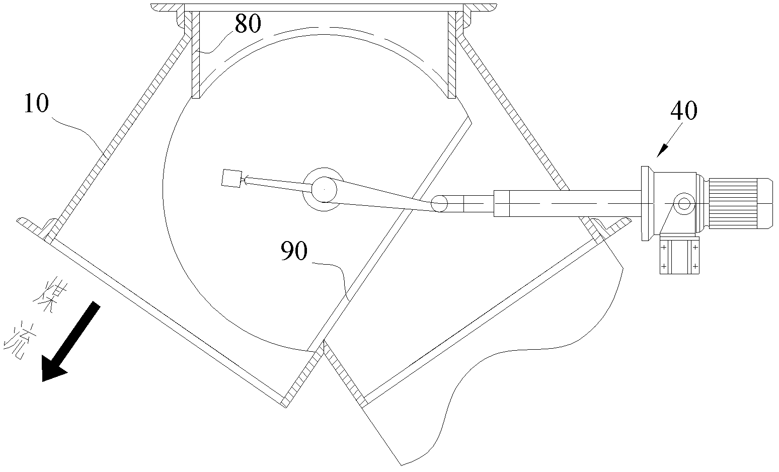
The disadvantage of the material distribution device with this structure is that the material is distributed by the boat-shaped baffle 90, and the boat-shaped baffle 90 can only select one of the left and right limit positions, and cannot complete the load distribution.
Moreover, when the material distribution device of this structure is used for on-line switching, material blocking will occur, and the strength of the boat-shaped baffle 90 is low. Therefore, the powder material device cannot complete the online switching, and the material must be emptied first. To switch to another way, the running time of the equipment is increased and resources are wasted

Method used


Image

  • Material distribution device
  • Material distribution device
  • Material distribution device

Examples


Embodiment Construction

[0029] Specific embodiments of the present invention will be described in detail below in conjunction with the accompanying drawings. It should be understood that the specific embodiments described here are only used to illustrate and explain the present invention, and are not intended to limit the present invention.

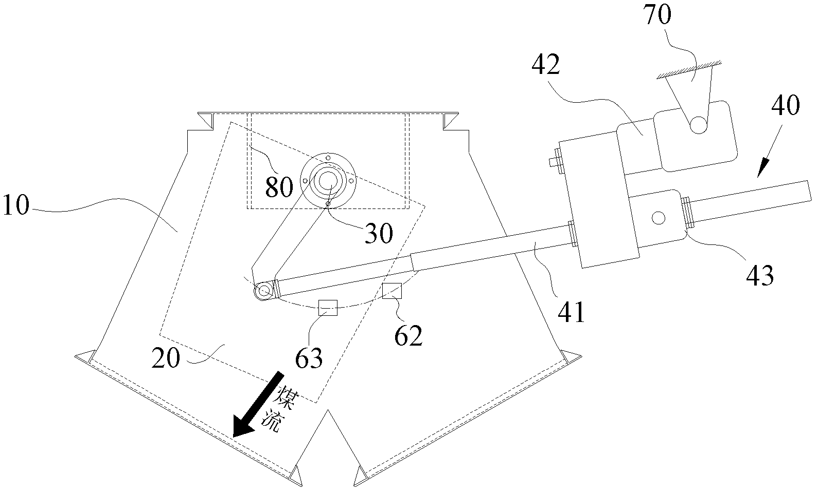
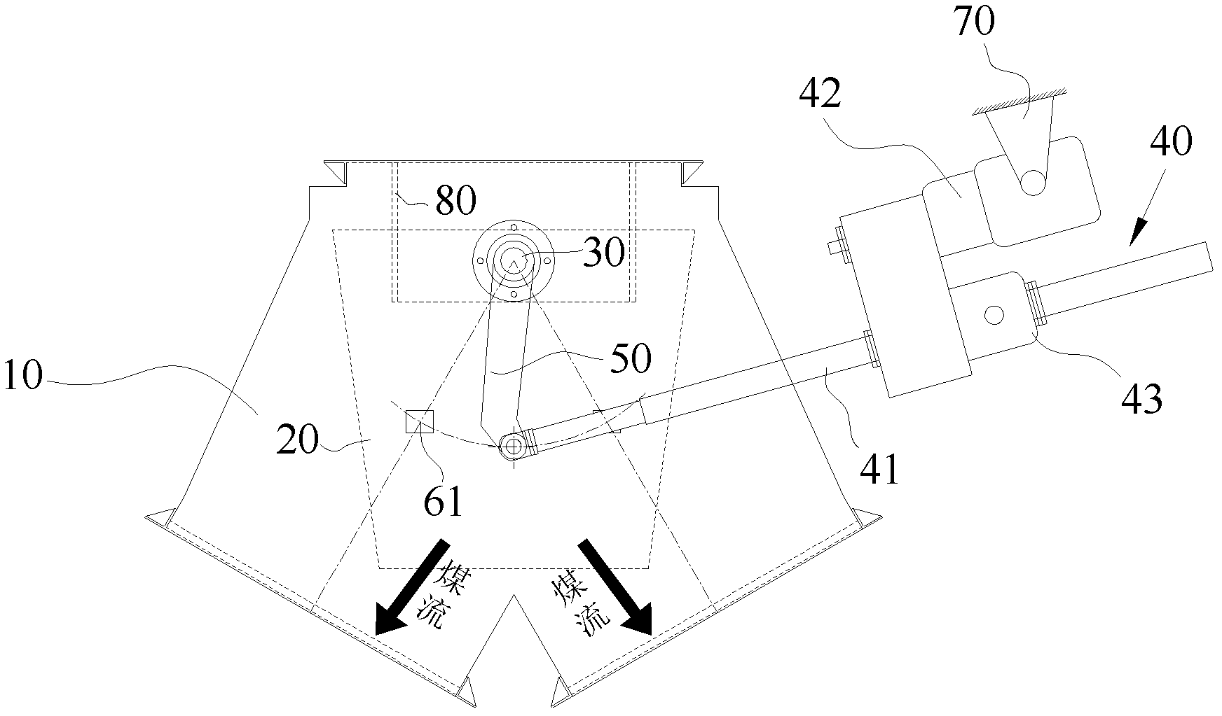
[0030] In the present invention, unless stated otherwise, the used orientation words such as "left, right" usually refer to Figure 2 to Figure 4 orientation in .

[0031] Such as Figures 2 to 4 As shown in , the present invention provides a material distribution device, which includes a three-way material distribution pipe 10, wherein the material distribution device also includes a material distribution device with openings at both ends arranged inside the three-way material distribution pipe 10 barrel 20 , the inlet of the material distribution barrel 20 communicates with the inlet of the three-way material distribution pipe 10 , and the outlet of the mate...


PUM


Abstract

The invention discloses a material distribution device which comprises a three-way material distribution pipe (10), and a material distribution barrel (20) with two opened ends, arranged in the three-way material distribution pipe (10), wherein the inlet of the material distribution barrel (20) is communicated with the inlet of the three-way material distribution pipe (10); and the outlet of the material distribution barrel (20) is selectively communicated with one or two outlets of the three-way material distribution pipe. According to the invention, the material distribution barrel is arranged in the three-way material distribution pipe, material enters from the inlet of the material distribution barrel and flows out from the outlet of the material distribution barrel, and the material blockage phenomenon can be avoided, as a result, the on-line switch of the material transportation is realized. And besides, the outlet of the material distribution barrel is communicated with the two outlets of the three-way material distribution pipe at the same time, and as a result, on-load distribution is realized during the material transportation.

Description

technical field [0001] The invention relates to the field of transportation of bulk materials, in particular to a material distribution device. Background technique [0002] Belt conveyor is a common material conveying equipment, and it is an important transportation equipment for conveying coal and iron ore in coal transfer terminals. The main components of the belt conveyor include drive rollers, reversing rollers, tensioning devices and belts. When transporting bulk materials, it is necessary to use a distribution device to realize the rapid reversing of materials. [0003] figure 1 Shown in is an existing material distribution device, which includes a three-way material distribution pipe 10 and a boat-shaped baffle 90 arranged in the three-way material distribution pipe 10 for guiding material distribution, the boat-shaped baffle The lower end of 90 is fixed on the three-way material distribution pipe 10 through the rotating shaft, and the rotating shaft is arranged o...

Claims


Application Information

Patent Timeline
Patent Type & Authority Applications(China)
IPC IPC(8): B65G47/46
Inventor 曾贺湛邹业庆
Owner CHINA SHENHUA ENERGY CO LTD
Learn More