Automatic filament charging machine

An automatic and wire machine technology, applied in the direction of conveyor objects, transportation and packaging, can solve the problems of automatic wire unloading machine running error, affecting the normal operation of the storage gate assembly, etc., to save installation space, improve work reliability, Wear-resistant effect

Inactive Publication Date: 2014-04-23
浙江世明电器有限公司
View PDF6 Cites 0 Cited by
  • Summary
  • Abstract
  • Description
  • Claims
  • Application Information

AI Technical Summary

Problems solved by technology

Among them, the outlet of the vibrator is provided with a splint, and the number of filaments sent each time from the outlet of the vibrator is controlled through the opening and closing gap of the splint. Once the opening and closing gap of the splint is wrong, several filaments will be sent out at the same time. The normal operation of the wire clamping conveying assembly and the storage gate assembly at the back resulted in more than one filament being placed in the V-shaped feeding trough on the final feeding track, and the automatic wire feeding machine ran incorrectly.

Method used


Image

  • Automatic filament charging machine
  • Automatic filament charging machine
  • Automatic filament charging machine

Examples


Embodiment Construction

[0028] The present invention will be further described below with reference to the accompanying drawings and specific embodiments.

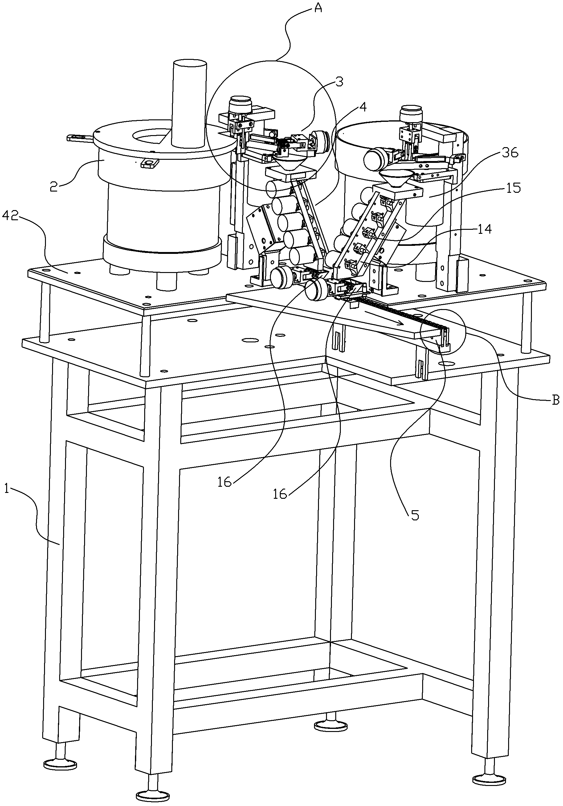
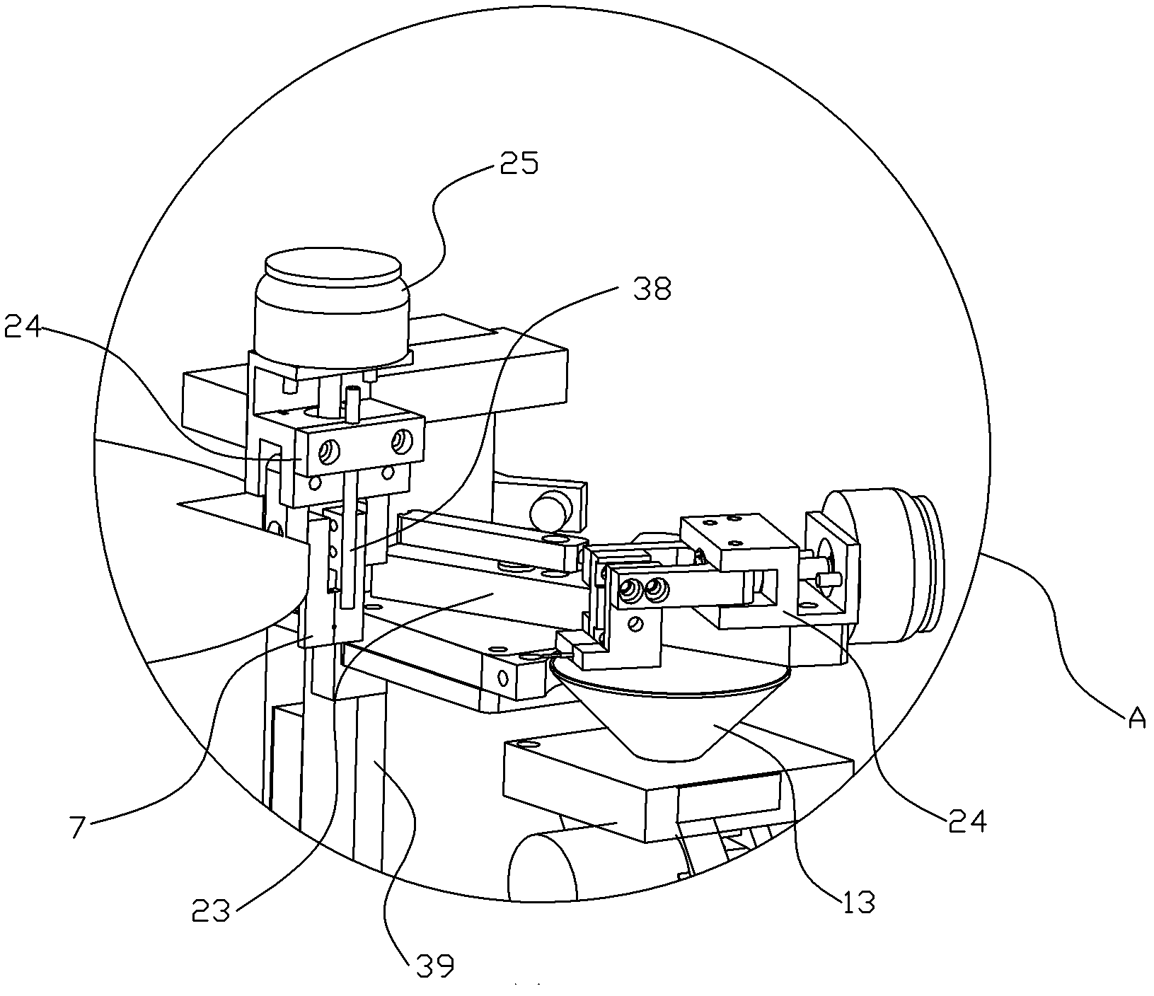
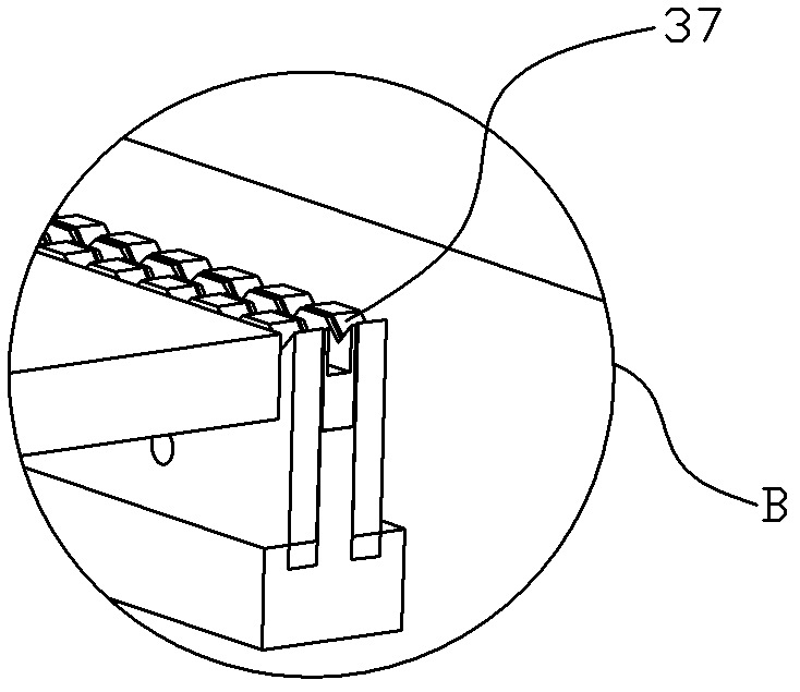
[0029] like Figures 1 to 12 As shown, the automatic wire feeding machine includes a frame 1, which is provided with a mounting table 42, and the mounting table is provided with a feeding track 5 with a V-shaped discharge chute 37, a controller (not shown in the figure), and two sets of the same The filament conveying device of the structure, each group of filament conveying devices includes a vibrating hopper 2 for conveying and conveying the filament in sequence, a wire clamping conveying assembly 3 and a storage gate assembly 4. The output end of the storage gate assembly 4 is located directly above the feeding track 5 Arranged in sequence along the advancing direction of the feeding track.

[0030] The storage gate assembly 4 includes a material receiving hopper 13, an inclined material guide trough 14 located at the lower end of the materia...


PUM


Abstract

The invention belongs to the field of machine manufacturing, particularly relates to an automatic filament charging machine for lamp filament transfer and conveyance. Aiming at the defect that the traditional discharging machine cannot provide only one lamp filament to the filament clamping conveyance component each time in a material supply link, the invention discloses an automatic filament charging machine which can provide only one lamp filament to the filament clamping conveyance component each time in the material supply link; two gate plates are arranged at a discharging end of a vibrating material hopper to form a split type gate, and only one lamp filament is supplied to the subsequent filament clamping conveyance component each time by virtue of the through hole on the gate, so that the lamp filaments can be clamped and conveyed one by one; and the misoperation of the traditional filament discharging machine that a plurality of lamp filaments are conveyed at the same time when the discharging end of the vibrating material hopper has a fault can be avoided, the operating and working reliability of the whole machine is improved.

Description

technical field [0001] The invention belongs to the field of machinery manufacturing, in particular to an automatic filament feeding machine for running and conveying filaments. Background technique [0002] The previous patent "Automatic Filament Unloading Machine" (Patent No. 201120069419.4) discloses a method that clamps the filaments one by one and then conveys them to the feeding track. Under the control of the controller, an automatic conveying machine is used instead of manually operated tweezers to manually clamp the filaments Put it on the feeding track, the automatic filament lowering machine is provided with two sets of filament conveying mechanisms with the same structure and the corresponding feeding track and filament detection unit, which realizes the mechanical automatic lowering of the filament, saves the manual filament filling process, and improves the Productivity. The outlet of the vibrator is provided with a splint, and the number of filaments sent out...

Claims


Application Information

Patent Timeline
Patent Type & Authority Patents(China)
IPC IPC(8): B65G47/14
Inventor 蒋伟成
Owner 浙江世明电器有限公司
Why Eureka
Try Eureka