Roller overlaying powder with thin-layer slag protection
A technology of powder and roll is applied in the field of roll surfacing welding powder and welding powder to achieve the effect of easy promotion, easy acquisition and improvement of welding seam forming.
- Summary
- Abstract
- Description
- Claims
- Application Information
AI Technical Summary
Problems solved by technology
Method used
Image

Examples
Embodiment 1
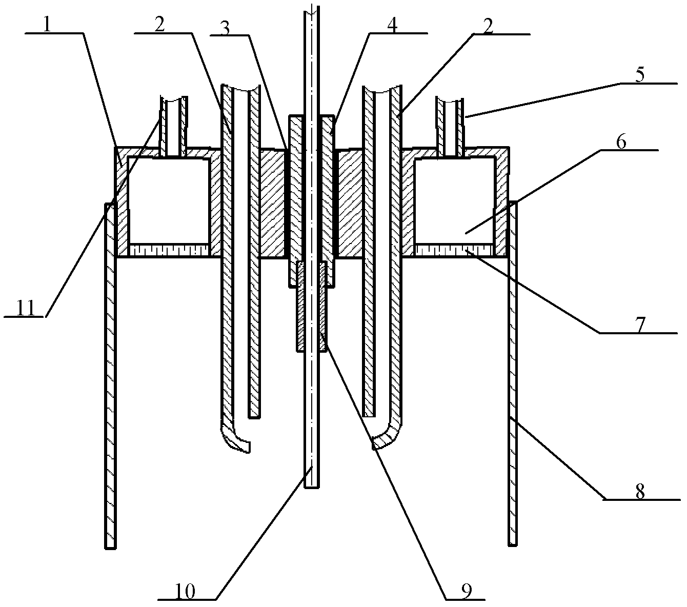
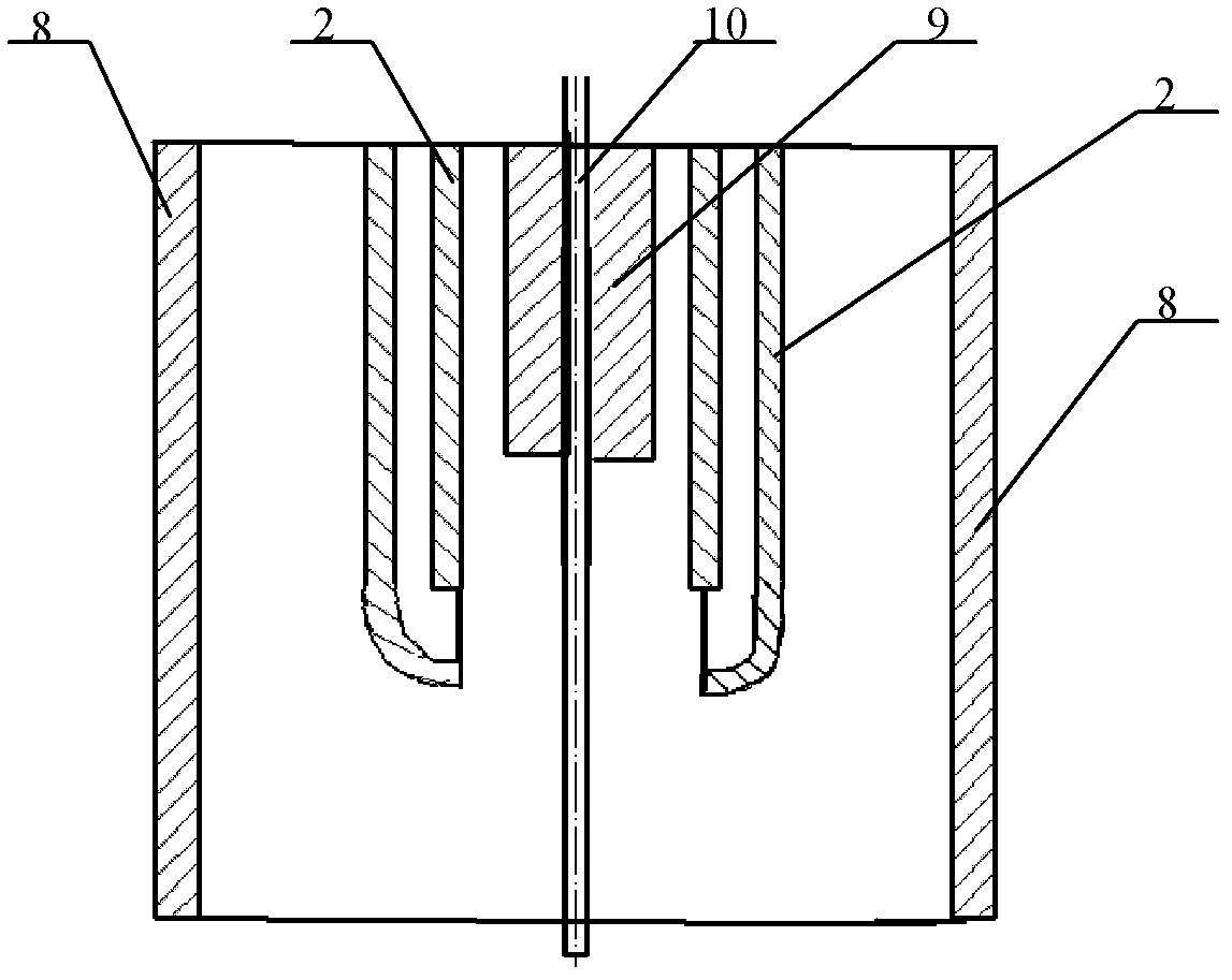
[0037] For the structure of the welding torch see figure 1 . The specific dimensions are as follows:
[0038] A conductive rod is provided on the center line of the welding torch. The conductive rod is a cylinder with an outer diameter of Φ6mm. The inner diameter of the conductive rod is Φ3mm. The conductive rod is made of red copper. The thickness of the insulating layer between the conductive rod and the connector is 1 mm, and the insulator is made of high-temperature-resistant rubber. The nominal diameter of the threaded hole on the lower surface of the conductive rod is M3 (ie 3mm), and the height is 5mm. It is matched with the conductive tip, and the conductive tip is a commercially available conductive tip for gas shielded welding.
[0039] The two powder feeding pipes are symmetrically installed on both sides of the conductive rod. The powder feeding pipes are fixed on the connecting piece through two through holes with a diameter of Φ5mm on the connecting piece. The ...
Embodiment 2
[0048] For the structure of the welding torch see figure 1 . The specific dimensions are as follows:
[0049] A conductive rod is provided on the center line of the welding torch. The conductive rod is a cylinder with an outer diameter of Φ7mm. The inner diameter of the conductive rod is Φ4mm. The conductive rod is made of red copper. The thickness of the insulating layer between the conductive rod and the connector is 2 mm, and the insulator is made of high-temperature-resistant rubber. The nominal diameter of the threaded hole on the lower surface of the conductive rod is M4, and the height is 8mm. It is matched with the conductive tip. The conductive tip is a commercially available conductive tip for gas shielded welding.
[0050] The two powder feeding pipes are symmetrically installed on both sides of the conductive rod. The powder feeding pipes are fixed on the connecting piece through two through holes with a diameter of Φ7mm on the connecting piece. The inner diamete...
Embodiment 3
[0059] For the structure of the welding torch see figure 1 . The specific dimensions are as follows:
[0060] A conductive rod is provided on the center line of the welding torch. The conductive rod is a cylinder with an outer diameter of Φ6.5mm. The inner diameter of the conductive rod is Φ2.5mm. The conductive rod is made of red copper. The thickness of the insulation layer between the conductive rod and the connector is 1.5mm, and the insulator is made of high temperature resistant plastic. The nominal diameter of the threaded hole on the lower surface of the conductive rod is M3 (that is, the nominal diameter is 3mm), and the height is 6mm. It is matched with the conductive tip. The conductive tip is a commercially available conductive tip for gas shielded welding.
[0061] The two powder feeding pipes are symmetrically installed on both sides of the conductive rod. The powder feeding pipes are fixed on the connecting piece through two through holes with a diameter of Φ6...
PUM
| Property | Measurement | Unit |
|---|---|---|
| particle size | aaaaa | aaaaa |
| thickness | aaaaa | aaaaa |
| diameter | aaaaa | aaaaa |
Abstract
Description
Claims
Application Information
 - R&D
- Intellectual Property
- Life Sciences
- Materials
- Tech Scout
- Unparalleled Data Quality
- Higher Quality Content
- 60% Fewer Hallucinations
Browse by: Latest US Patents, China's latest patents, Technical Efficacy Thesaurus, Application Domain, Technology Topic, Popular Technical Reports.
© 2025 PatSnap. All rights reserved.Legal|Privacy policy|Modern Slavery Act Transparency Statement|Sitemap|About US| Contact US: help@patsnap.com