Light source module and area light source module using the same

A light source module, surface light source technology, applied in the direction of light source, electric light source, point light source, etc., can solve the problem of affecting the service life of the light-emitting element, the luminous efficiency of the light-emitting element, etc.

Inactive Publication Date: 2012-07-25
LEXTAR ELECTRONICS CORP
View PDF5 Cites 2 Cited by
  • Summary
  • Abstract
  • Description
  • Claims
  • Application Information

AI Technical Summary

Problems solved by technology

In addition, the heat sink is usually fixed on the backplane of the light source module by screw locking or bonding with a low thermal conductivity thermally conductive adhesive, but the use of thermally conductive adhesive will cause the heat generated by the light-emitting element to still accumulate here for heat conduction The heat cannot be conducted to the backplane of the light source module and the outside world, which will affect the service life of the light-emitting element and the luminous efficiency of the light-emitting element

Method used


Image

  • Light source module and area light source module using the same
  • Light source module and area light source module using the same
  • Light source module and area light source module using the same

Examples


Embodiment Construction

[0044] In the light source module and the surface light source module of this embodiment, one end of the heat pipe is connected to the heat sink to absorb heat from the heat sink, and the other end of the heat pipe extends outward from the heat sink to release heat. The cooling liquid in the heat pipe can evaporate upward after being heated at the heat-absorbing end and move toward the heat-dissipating end. After the steam condenses and releases heat, it becomes a liquid and flows downward through the siphon to the heat-absorbing end. Such a continuous periodic cycle can quickly dissipate the heat absorbed by the heat sink through the cooling liquid to achieve the cooling effect.

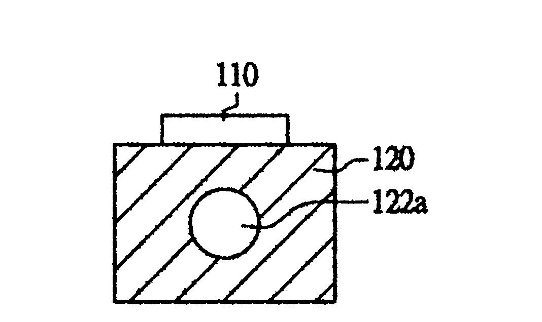
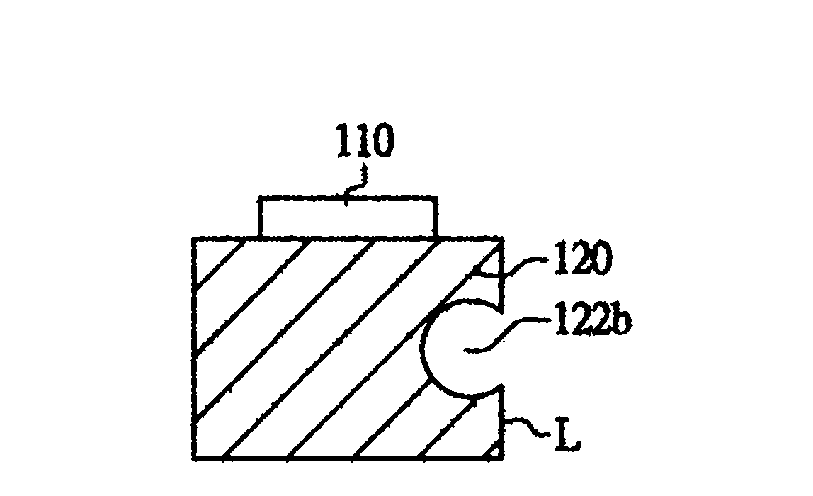
[0045] Please refer to figure 1 , Figure 2A , Figure 2B and Figure 2C ,in figure 1 A schematic diagram illustrating a light source module according to an embodiment, Figure 2A , Figure 2B and Figure 2C The cross-sectional schematic diagrams of different types of grooves are respectively...


PUM


Abstract

The invention discloses a light source module and an area light source module using the same, wherein the light source module includes a light-emitting element, a heat radiating sheet and a heat conducting pipe. The heat radiating sheet is arranged at the bottom of the light-emitting element. The heat radiating sheet is provided with a groove. The heat conducting pipe is connected with one side surface of the heat radiating sheet. The heat conducting pipe is provided with a heat absorbing end and a heat releasing end. The heat absorbing end of the heat conducting pipe is inserted into the groove and the heat is conducted to the outside through the heat releasing end.

Description

technical field [0001] The invention relates to a light source module and a surface light source module, and in particular to a light source module and a surface light source module which increase the heat dissipation capacity of a heat sink. Background technique [0002] Generally speaking, the light-emitting element is pasted on the heat-absorbing surface of the heat sink with a heat-conducting adhesive. In order to reduce the thermal resistance of the heat-conducting glue, silver glue with high thermal conductivity is mainly used, so the heat is quickly transferred from the light-emitting element to the heat sink, and it is less likely to accumulate on the heat-conducting glue. In addition, the heat sink is usually fixed on the backplane of the light source module by screw locking or bonding with a low thermal conductivity thermally conductive adhesive, but the use of thermally conductive adhesive will cause the heat generated by the light-emitting element to still accumu...

Claims


Application Information

Patent Timeline
IPC IPC(8): F21S2/00F21V29/00F21V8/00F21Y101/02F21K9/235F21V29/70F21Y115/10
Inventor 刘诚议
Owner LEXTAR ELECTRONICS CORP
Why Eureka
Try Eureka