
Blackening furnace

A furnace cover and furnace wall technology, which is applied in the field of blackening furnaces, can solve the problems of inability to increase the pressure of the furnace cavity, uneven thickness, and small thickness of the blackening layer, so as to achieve a convenient and fast opening process, good sealing effect and ideal sealing performance. Effect

Inactive Publication Date: 2012-07-25
宁波东方加热设备有限公司
View PDF1 Cites 11 Cited by
  • Summary
  • Abstract
  • Description
  • Claims
  • Application Information

AI Technical Summary

Problems solved by technology

[0003] Because the furnace cover of the blackening furnace in the prior art is manually opened and closed and then locked by screws, there are the following defects: every time the furnace cover is opened or closed, the screws need to be manually tightened or loosened, and the process is cumbersome, time-consuming and laborious , and, more importantly, the furnace cover is locked by screws, and its sealing effect is very poor, which leads to the inability to increase the pressure in the furnace cavity, which generally can only reach about 0.3 bar. For the workpiece, the thickness of the blackened layer is small and uneven, and the effect of blackened heat treatment is not ideal
Although there is a sealing ring between the output shaft of the motor and the through hole of the furnace cover, due to the relative rotation between the output shaft of the motor and the sealing ring, that is, the seal is a dynamic ring seal, the sealing effect is not ideal, which also makes the inside of the furnace cavity The pressure cannot be increased, and the workpiece is blackened and the heat treatment effect is poor

Method used


Image

  • Blackening furnace
  • Blackening furnace
  • Blackening furnace

Examples


Embodiment Construction

[0021] The present invention will be further described below in conjunction with the accompanying drawings and specific embodiments.

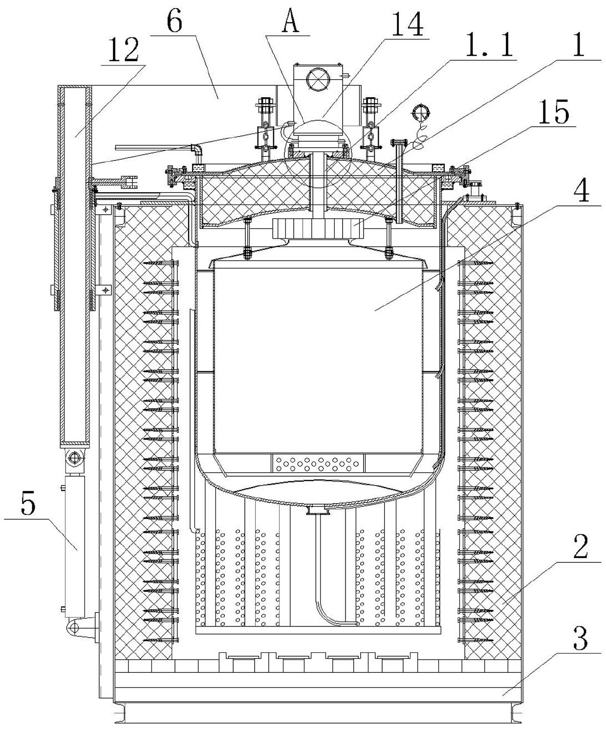
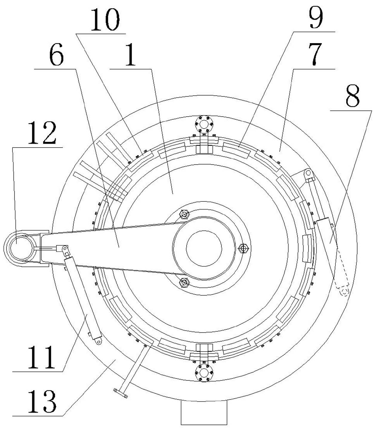
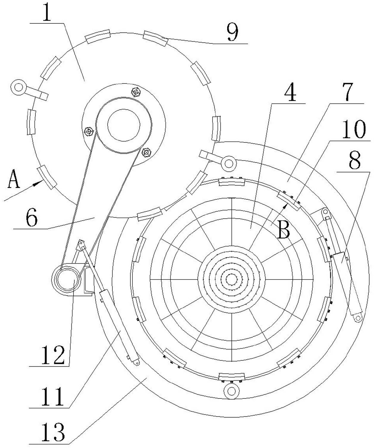
[0022] Such as figure 1 , figure 2 , image 3 , Figure 4 , Figure 5 , Image 6 , Figure 7 Shown, blackening furnace of the present invention, it comprises furnace cover 1, furnace wall 2, base 3, lifting cylinder 5, rocking arm 6, the 3rd cylinder 11, motor 14 and wind wheel 15. The furnace cover 1, the furnace wall 2 and the base 3 surround a synthetic furnace chamber 4. There is a through hole 1.1 through the furnace cover 1, and the output shaft 14.1 of the motor 14 is fixed to the wind wheel 15 in the furnace chamber 4 through the through hole 1.1 of the furnace cover 1. The lower end of the shell of the motor 14 is a flange end 14.2, the top of the furnace cover 1 is fixed with a flange 1.2, the flange end 14.2 of the motor 14 is fixed to the flange 1.2 of the furnace cover 1, and the flange end 14.2 of the motor 14 A sealing r...


PUM


Abstract

The invention discloses a blackening furnace. The blackening furnace comprises a furnace cover (1), a furnace wall (2), a base (3), a lifting cylinder (5) and a rocker arm (6), wherein the furnace cover (1), the furnace wall (2) and the base (3) enclose to form a furnace chamber (4); the piston rod of the lifting cylinder (5) is connected with the outer end of the rocker arm (6); the inner end of the rocker arm (6) is fixed with the furnace cover (1); the cylinder wall of the lifting cylinder (5) is fixed with the furnace wall (2); a horizontal annular groove is formed in the inner wall of the furnace wall (2); a self-locking ring which can rotate along the circumferential direction of the annular groove is arranged in the annular groove; a second cylinder used for rotating the self-locking ring is arranged on the self-locking ring; a radially outwards-convex bump is arranged on the outer circumferential surface of the furnace cover (1); and a radially inwards-concave locking block used for rotationally locking the bump is arranged on the inner circumferential surface of the self-locking ring. The blackening furnace can be opened or locked conveniently and rapidly; and moreover, the air pressure in a furnace chamber can be improved.

Description

technical field [0001] The invention relates to the field of heat treatment equipment, in particular to a blackening furnace. Background technique [0002] The blackening furnace is a furnace body that heat-treats powder metallurgy workpieces to blacken the surface of the workpieces to form a protective layer. It includes a furnace cover, a furnace wall and a base. In the furnace cavity, the furnace cover is hinged on the top of the furnace wall. The furnace cover is provided with a plurality of holes for screws to pass through. The top of the furnace wall is provided with threaded holes corresponding to the holes on the furnace cover. The lower surface of the furnace cover is fixed with sealing ring. When it is necessary to close the furnace cover to heat treat the workpiece, cover the opening of the furnace cavity with the furnace cover, and then lock the furnace cover with a screw that passes through the hole of the furnace cover and tightens the screw in the threaded ho...

Claims


Application Information

Patent Timeline
IPC IPC(8): C23C8/06C23C8/16F27B5/04F27B5/06
Inventor 陈金国陈文芳
Owner 宁波东方加热设备有限公司
Learn More