
Indirect measurement method based tool parameter calibration method for high-precision drilling robot

A tool parameter and calibration method technology, applied in manufacturing tools, measuring/indicating equipment, metal processing equipment, etc., can solve the problems of large errors, large errors, and difficulty in adapting to accuracy requirements in the calibration results, so as to achieve convenient application, improve Calibration accuracy and the effect of improving the scope of application

Active Publication Date: 2012-07-25
南京航浦机械科技有限公司
View PDF5 Cites 19 Cited by
  • Summary
  • Abstract
  • Description
  • Claims
  • Application Information

AI Technical Summary

Problems solved by technology

Document "Niu Xuejuan, Liu Jingtai. Robot Tool Coordinate System Calibration Based on Singular Value Decomposition [J]. Automation and Instrumentation, 2008, 3:1-4." Proposed a robot tool parameter calibration method called the three-point five-step method , the position parameters and attitude parameters of the tool parameters can be calibrated at the same time, but in the calibration process, some teaching methods cannot be accurately achieved, so even though the least squares optimization method is used, the calibration results will still have large errors. Suitable for applications requiring high precision
[0004] Most of the above-mentioned methods need to use certain external calibration tools and require more human participation in the calibration process, which will introduce large errors and make it difficult to adapt to occasions that require particularly high precision.

Method used


Image

  • Indirect measurement method based tool parameter calibration method for high-precision drilling robot
  • Indirect measurement method based tool parameter calibration method for high-precision drilling robot
  • Indirect measurement method based tool parameter calibration method for high-precision drilling robot

Examples


Embodiment Construction

[0022] The steps of the tool parameter calibration method of the high-precision hole-making robot based on the indirect measurement method in the present invention are as follows:

[0023] Step 1: Use the laser tracker to establish the robot coordinate system;

[0024] The steps to establish the association between the laser tracker and the robot base coordinate system are:

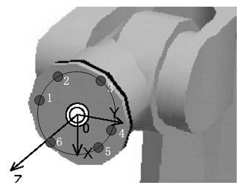
[0025] 1) The spherical fixed reflector SMR is fixed on the TCP of the end effector, and the position (angle) of the A2 to A6 axes is kept fixed. By rotating the A1 axis, a series of points on the circumference are measured with the FARO laser tracker ;

[0026] 2) Use the CAM2 Measure software that comes with FARO to sequentially fit the measurement points obtained in step 1) into a plane and a circle to obtain the theoretical coordinates of the center of the circle;

[0027] 3) Measure a series of points on the plane of the robot base and fit a plane, and then offset the plane by the SMR radius;

[0...


PUM


Abstract

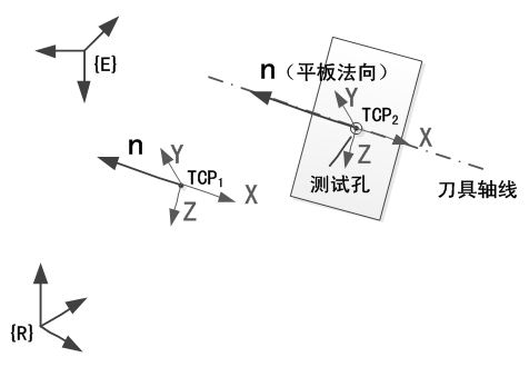
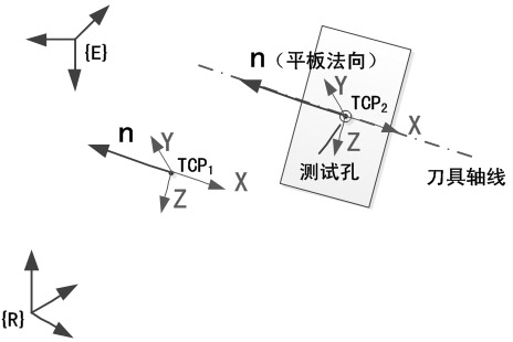
The invention discloses an indirect measurement method based tool parameter calibration method for a high-precision drilling robot, which relates to two TCPs (tool center points), wherein one TCP can be determined by directly measuring while the other TCP is a virtual tool point on the axis of a tool of a drilling device. A calibration flat plate is drilled to fix the position of the virtual tool point when the tail end of the robot is controlled to reach a certain position, and a robot kinematic model is used for determining parameters of the virtual tool point. Procedures which are difficulty in guaranteeing of precision of point alignment and the like during tool parameter calibration of a traditional robot are avoided, so that calibration precision is improved. Application range of the method is widened, the problem that the virtual tool point cannot be measured is solved, the whole calibration process can be programmed to be fixed, and corresponding program parameters can be modified for adaption even productive tasks change, so that application of the method in industrial fields can be facilitated.

Description

technical field [0001] The invention relates to a tool parameter calibration method of a high-precision hole-making robot based on an indirect measurement method, and belongs to the technical field of industrial robot calibration. Background technique [0002] In recent years, with the development of industrial robot technology and the urgent need of automation and flexible assembly in aircraft manufacturing industry. In the process of aircraft manufacturing, the use of industrial robots for automatic flexible assembly and component processing such as drilling, riveting, painting, welding, etc. can greatly improve the efficiency and quality reliability of aircraft production. In practical applications, the robot completes various tasks by installing different tools at the end. Usually, the tool parameters need to be calibrated before the operation, and the accuracy of the tool parameters has a direct impact on the positioning accuracy and trajectory accuracy of the robot. ...

Claims


Application Information

Patent Timeline
Patent Type & Authority Applications(China)
IPC IPC(8): B23Q17/22B23Q17/24
Inventor 田威廖文和周炜沈建新周卫雪贺美华
Owner 南京航浦机械科技有限公司
Learn More