
Device For Machining The Narrow Surfaces Of Preferably Board-shaped Workpieces

A technology for processing workpieces and workpieces, applied in metal processing equipment, wood processing equipment, manufacturing tools, etc., can solve the problems of increasing downtime and time required, and achieve the effects of simple layout, reduced weight, and high system rigidity

Active Publication Date: 2014-12-24
HOMAG HOLZBEARBEITUNGSSYST
View PDF6 Cites 0 Cited by
  • Summary
  • Abstract
  • Description
  • Claims
  • Application Information

AI Technical Summary

Problems solved by technology

This takes time and thus increases machine downtime

Method used


Image

  • Device For Machining The Narrow Surfaces Of Preferably Board-shaped Workpieces
  • Device For Machining The Narrow Surfaces Of Preferably Board-shaped Workpieces
  • Device For Machining The Narrow Surfaces Of Preferably Board-shaped Workpieces

Examples


Embodiment Construction

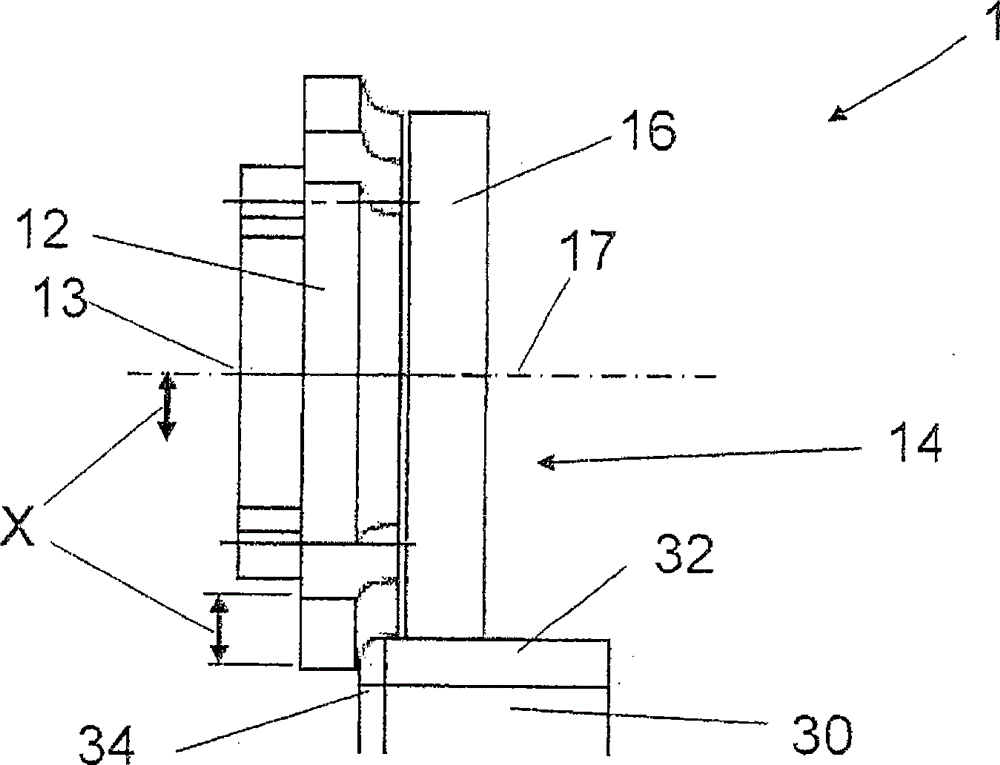
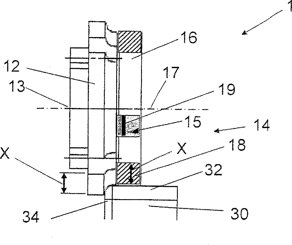
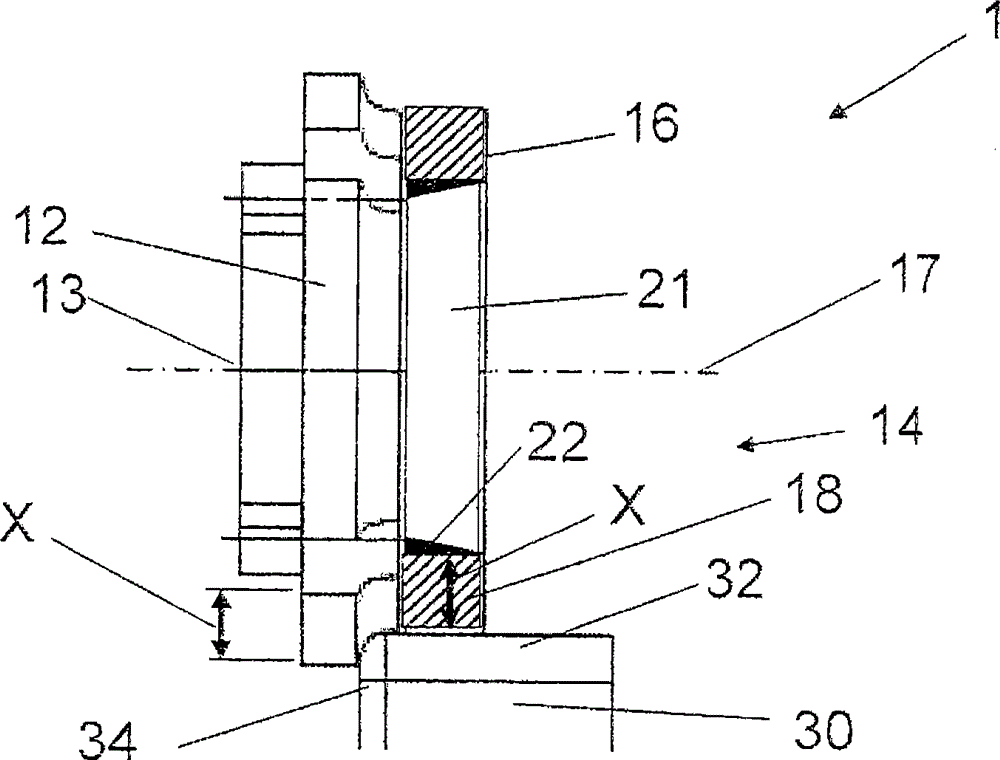
[0023] figure 1 Shows a schematic sectional view of a conventional device 1 for processing preferably floor-shaped workpieces 30 (which are preferably made at least in sections from wood, timber, plastic, etc.), with The tool 12 and the contact roller 16. The tool 12 is in this exemplary embodiment a milling cutter 12 whose axis runs horizontally in the drawing. The tool axis 13 runs on an axis of rotation 17 of a contact roller 16 of the contact device 14 arranged coaxially to the milling cutter 12 . Both the milling tool 12 and the contact rollers 16 rest on the front side on a workpiece 30 , which is shown like a rectangle.

[0024] An edge 34 is glued to the workpiece 30 on the left in the figure. The vertical elevation of edge 34 adjoining edge 32 of workpiece 30 is milled with milling cutter 12 . The axial offset of the tool is shown by the double arrow X, which is necessary in order to balance the corresponding tool wear, which is also shown by the double arrow X, w...


PUM


Abstract

The invention relates to a device for machining preferably board-shaped workpieces, preferably made at least in segments of wood, wood materials, plastic, or the like, having a tool arrangement acting on the workpiece and comprising at least one tool, and a contact device having at least one contact roller disposed rotatably about the rotary axis thereof adjacent to the tool and controlling the position of the tool relative to the workpiece, wherein a diameter of the contact roller is adjustable.

Description

technical field [0001] The invention relates to a device for machining narrow surfaces of preferably floor-shaped workpieces, which are made at least in sections of wood, timber, plastic or the like. [0002] Such plate-shaped workpieces are reprocessed, for example, in the furniture industry. Depending on the tolerances of the material strength, machining on the narrow side of the workpiece (eg profiling or remachining of glued edges) is carried out by means of a copying method (Kopierverfahren) in order to achieve a workpiece along the actual workpiece geometry guide. Clamping-dependent positional tolerances of the workpiece can also be compensated for in this way. [0003] In replica machining, a contact device is provided with contact elements, usually contact rollers, which roll on the workpiece surface and control the position of the tool relative to the workpiece. Background technique [0004] A device of the type mentioned at the outset is known from EP 08 17 0074...

Claims


Application Information

Patent Timeline
Patent Type & Authority Patents(China)
IPC IPC(8): B23C3/12B23C5/12B27D5/00
CPCB23C2260/08B27D5/006B23C3/126B23C2220/40
Inventor P·拉特格伯W·卡尔姆巴赫
Owner HOMAG HOLZBEARBEITUNGSSYST
Learn More