
Inkjet printing device and method for replacing a print head

a printing device and print head technology, applied in printing and other directions, can solve the problems of insufficient reduction of ink stain damage to the surroundings, inability to provide a reduction method, and damage to the area around the print head or the ink supply path, so as to inhibit ink scattering and ink leakage, increase the size of the inkjet printing device

Active Publication Date: 2012-03-01
CANON KK
View PDF11 Cites 18 Cited by
  • Summary
  • Abstract
  • Description
  • Claims
  • Application Information

AI Technical Summary

Benefits of technology

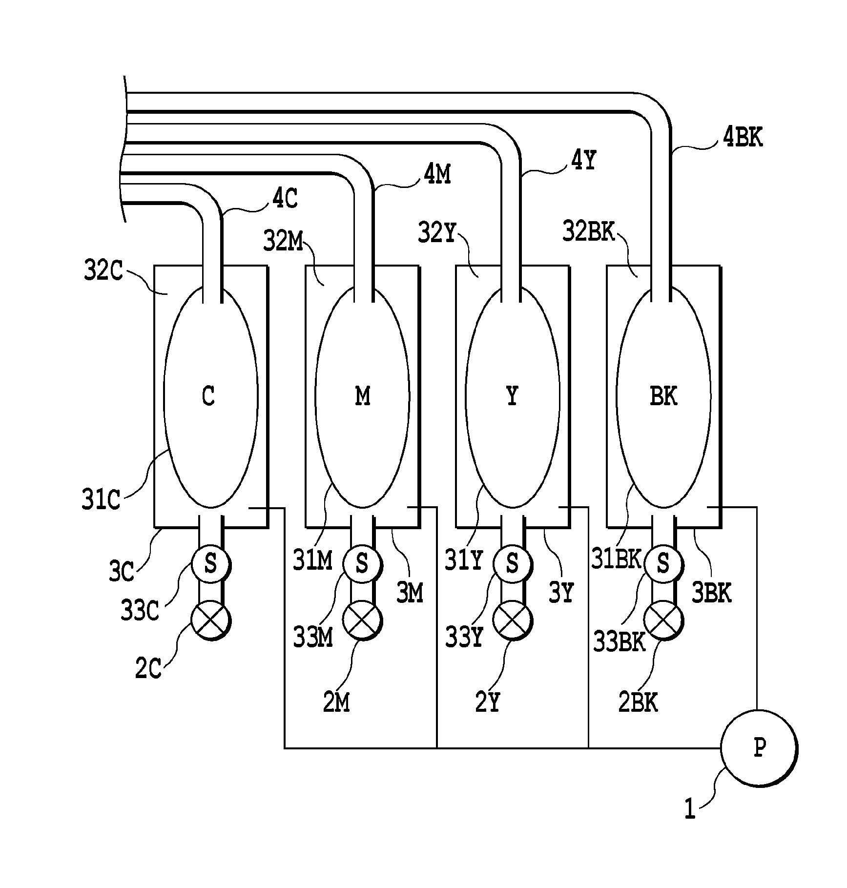
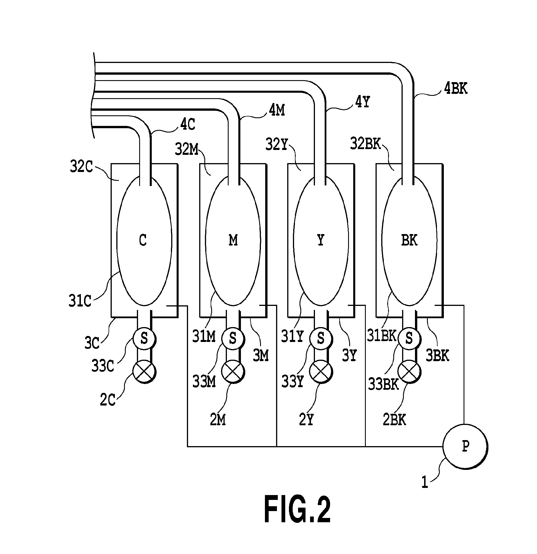
[0010]It is an object of the present invention to provide an inkjet printing device capable of inhibiting ink scattering and ink leaking at the time of replacing a print head without causing complexity of an ink supply unit and an increase in size of the inkjet printing device.
[0012]According to the present invention, it is possible to provide an inkjet printing device capable of inhibiting the ink scattering and ink leaking at the time of replacing the print head to reduce an ink stain at the time of replacing the print head and to achieve proper replacement of the print head, without causing complexity of an ink supply needle and an increase in size of the inkjet printing device.

Problems solved by technology

However, this method has a risk of residual ink in the print head or the ink supply path leaking from there to result in an ink stain damaging an area around the print head or the ink supply path when or after the print head is or has been removed.
Accordingly, when the print head is removed under such conditions, risks of scattering and dripping of the residual ink remaining in the joint between the print head and the ink supply path still remain.
The methods provide an inadequate reduction in an ink stain damaging the surroundings.
However, employment of such a structure including the ink-suction hole provided in the ink supply needle and the negative-pressure generating mechanism for suction provided in the ink supply path, as described in Japanese Patent Laid-Open No. 2001-018412, provides a complicated structure of an ink supply unit because of replacement of the print head.
As a result, this structure brings in complexity, an increase in size or cost, and the like in the inkjet printing device.

Method used


Image

  • Inkjet printing device and method for replacing a print head
  • Inkjet printing device and method for replacing a print head
  • Inkjet printing device and method for replacing a print head

Examples


first embodiment

[0034]FIG. 6 is a control flow chart of print-head replacement sequence 1 according to a first embodiment.

[0035]In the inkjet printing device according to the first embodiment of the present invention, if an operation for removing the print head 5 is requested because, for example, the need for replacement of the print head 5 arises (step S601), the pressure pump 1 of the main ink tank 3 is stopped (step S602). Then, the atmosphere communication valve 2 mounted in a pressurized section of the tube 4 is switched to the open position (step S603). This operation releases the pressurization state in the tube 4, so that the pressure in the tube 4 is reduced substantially to an atmospheric pressure. However, if the print head is detached in this condition, a residual ink remaining in the joint 45 between the print head 5 and the tube 4 is scattered by a residual pressure in the tube 4 or the detaching operation, possibly giving rise to ink dripping. To address it, the present invention pe...

second embodiment

[0038]FIG. 7 is a control flow chart of print-head replacement sequence 2 according to a second embodiment.

[0039]In the inkjet printing device according to the second embodiment of the present invention, if an operation for removing the print head 5 is requested because, for example, of the need for replacement of the print head 5 (step S701), the pressure pump 1 of the main ink tank 3 is stopped (step S702). Then, the atmosphere communication valve 2 mounted in a pressurized section of the tube 4 is switched to the open position (step S703). This operation releases the pressurization state in the tube 4, so that the pressure in the tube 4 is reduced substantially to an atmospheric pressure.

[0040]In the present invention, an auxiliary ejection operation 1 for ejecting ink is performed after the atmosphere communication valve 2 in the pressurization section has been switched to the open position (step S704). When the auxiliary ejection operation 1 is performed, the tube 4 is not pres...


PUM


Abstract

An inkjet printing device, comprising: a print head for ejecting ink; a carriage provided with the print head detachably mounted thereon for moving the print head; an ink tank placed outside the carriage for storing ink; an ink supply path for supplying ink from the ink tank to the print head; and a discharge unit for discharging ink in the print head, wherein before the print head is detached from the carriage, the discharge unit discharges the ink in the print head.

Description

BACKGROUND OF THE INVENTION[0001]1. Field of the Invention[0002]This invention relates to an inkjet printing device and a method for replacing a print head of an inkjet printing device. More particularly, this invention relates to techniques for connecting an ink tank and a print head with a supply path such as an ink supply tube and preventing ink from leaking from the supply path when the print head is removed from the supply path for print-head replacement or the like.[0003]2. Description of the Related Art[0004]In the inkjet printing devices, there is known a method for connecting an ink tank and a print head with an ink supply path such as a tube to supply ink from the ink tank to the print head. In this method, the ink tank is typically mounted in a fixed position within the inkjet printing device. The ink tank and the print head mounted on a carriage are connected to each other by use of the ink supply path such as the tube, thereby supplying the ink from the ink tank to the ...

Claims


Application Information

Patent Timeline
IPC IPC(8): B41J2/175
CPCB41J2/17509
Inventor HAMASAKI, YUJITAKAHASHI, ATSUSHINAKAGAWA, YOSHINORIKITABATAKE, NOBUHIROYAMAMOTO, NAOMI
Owner CANON KK
Learn More