
Device for automatically and synchronously assembling magnetic shoes and U-shaped spring of direct-current motor

A technology for direct current motors and assembly devices, which is applied in the direction of electromechanical devices, electric components, and manufacturing motor generators. It can solve the problems of high labor intensity, low production efficiency, and low assembly quality, and reduce labor intensity. The effect of production efficiency

Active Publication Date: 2012-07-18
SHANGHAI KELAI MECHATRONICS ENG CO LTD
View PDF4 Cites 8 Cited by
  • Summary
  • Abstract
  • Description
  • Claims
  • Application Information

AI Technical Summary

Benefits of technology

This technology allows for efficient and accurate assembly of motors with multiple components such as an AC brushless direct current (BLDC) or linear induction machine (LARM). It eliminates the step of applying adhesive before installing each component separately by hand, reducing manual effort required while ensuring proper alignment between them. Additionally, it simplifies the manufacture process without requiring special equipment that could harm either part being assembled on top. Overall, this technology streamlined the way we install these parts into electric machines more efficiently and accurately than previous methods.

Problems solved by technology

This patented describes how to securely hold up certain parts called the upright plate or rotor shaft inside a housing made from metal material like iron without damaging them during manufacturing processes such as welding. To ensure proper alignment of these components, there has been developed various methods involving mounting special ferrous materials onto the component's surfaces beforehand. However, current methods have limitations due to factors including accuracy required by the installer, difficulty in attaching large amounts of resilient material, and potential damage caused by excessive forces applied through the fiberglass reinforcement used in the case of AC machines.

Method used


Image

  • Device for automatically and synchronously assembling magnetic shoes and U-shaped spring of direct-current motor
  • Device for automatically and synchronously assembling magnetic shoes and U-shaped spring of direct-current motor
  • Device for automatically and synchronously assembling magnetic shoes and U-shaped spring of direct-current motor

Examples


Embodiment Construction

[0026] The preferred embodiments of the present invention are given and described in detail below in conjunction with the accompanying drawings, so as to better understand the functions and characteristics of the DC motor magnetic tile and U spring synchronous automatic assembly device of the present invention.

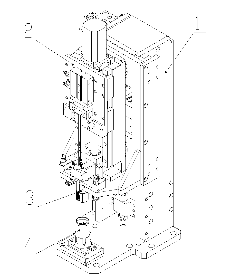
[0027] More specifically refer to the attached Figure 1-10 According to the present invention, the DC motor magnetic tile and U spring synchronous automatic assembly device includes a positioning device 1, a U spring closing device 2, a magnetic tile vacuum adsorption device 3 and a motor housing placement device 4, such as figure 1 shown.

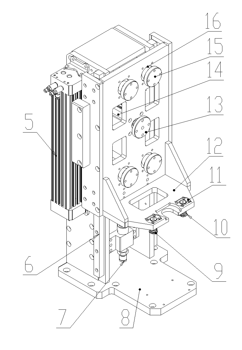
[0028] Such as figure 2 As shown, the positioning device 1 adopts a double-layer structure, and the L-shaped mounting bracket 8 is the basis of the device, and the upper and lower telescopic cylinders 5, the main guide rail 6, and the limit post 7 are fixed on its vertical surface, and there are fixed on its horizontal surface....


PUM


Abstract

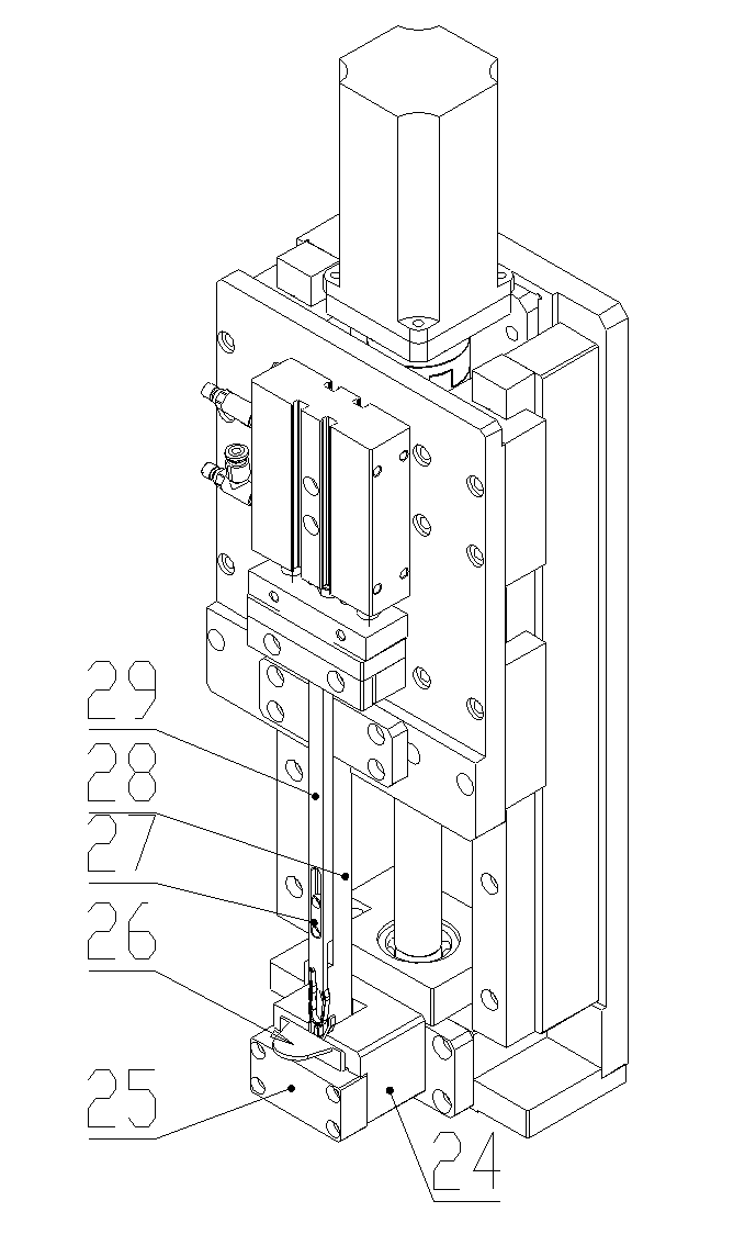
The invention provides a device for automatically and synchronously assembling magnetic shoes and a U-shaped spring of a direct-current motor. The device comprises a positioning device, a U-shaped spring closing device, a magnetic shoe vacuum suction device and a motor shell placing device, wherein the positioning device is provided with a vertical straight line main guide rail and a longitudinal supporting straight bearing; with the adoption of the U-shaped spring closing device, the U-shaped spring is forced to be closed through a guide groove of a U-shaped spring closing guide block, so that the closing state of the U-shaped spring is kept by a U-shaped spring closing rod driven by a closing air cylinder before mounting the U-shaped spring in the motor shell; the magnetic shoe vacuum suction device fixes magnetic shoes with an accurate standard at accurate positions; and the motor shell placing device is used for positioning and supporting the motor shell. With the adoption of the device provided by the invention, the U-shaped spring and the magnetic shoes can be automatically and synchronously assembled; furthermore, the U-shaped spring cannot scrap the lateral faces of the magnetic shoes in an assembling process; and a position distance of mounting the U-shaped spring between the two magnetic shoes is precisely controlled by using serve drive accurate positioning properties. Therefore, the operation labor intensity is effectively reduced, and the assembly operation efficiency and the assembly quality of the magnetic shoes and the U-shaped spring are improved.

Description


Claims


Application Information

Patent Timeline
Owner SHANGHAI KELAI MECHATRONICS ENG CO LTD
Learn More