
Fuel cell

A fuel cell and battery unit technology, applied to fuel cells, fuel cell components, circuits, etc., can solve problems such as increased usage, high unit prices of components, and large separator 1 area

Active Publication Date: 2012-07-18
HONDA MOTOR CO LTD
View PDF4 Cites 5 Cited by
  • Summary
  • Abstract
  • Description
  • Claims
  • Application Information

AI Technical Summary

Problems solved by technology

[0007] However, since the manifold filling ports 3a, 3b, 3c, and 3d are formed through the above-mentioned partition plate 1, the area of ​​the partition plate 1 becomes considerably large.
As a result, the amount of raw materials used, such as expensive stainless steel, is increased, resulting in an increase in the unit price of parts.

Method used


Image

  • Fuel cell
  • Fuel cell
  • Fuel cell

Examples


Embodiment Construction

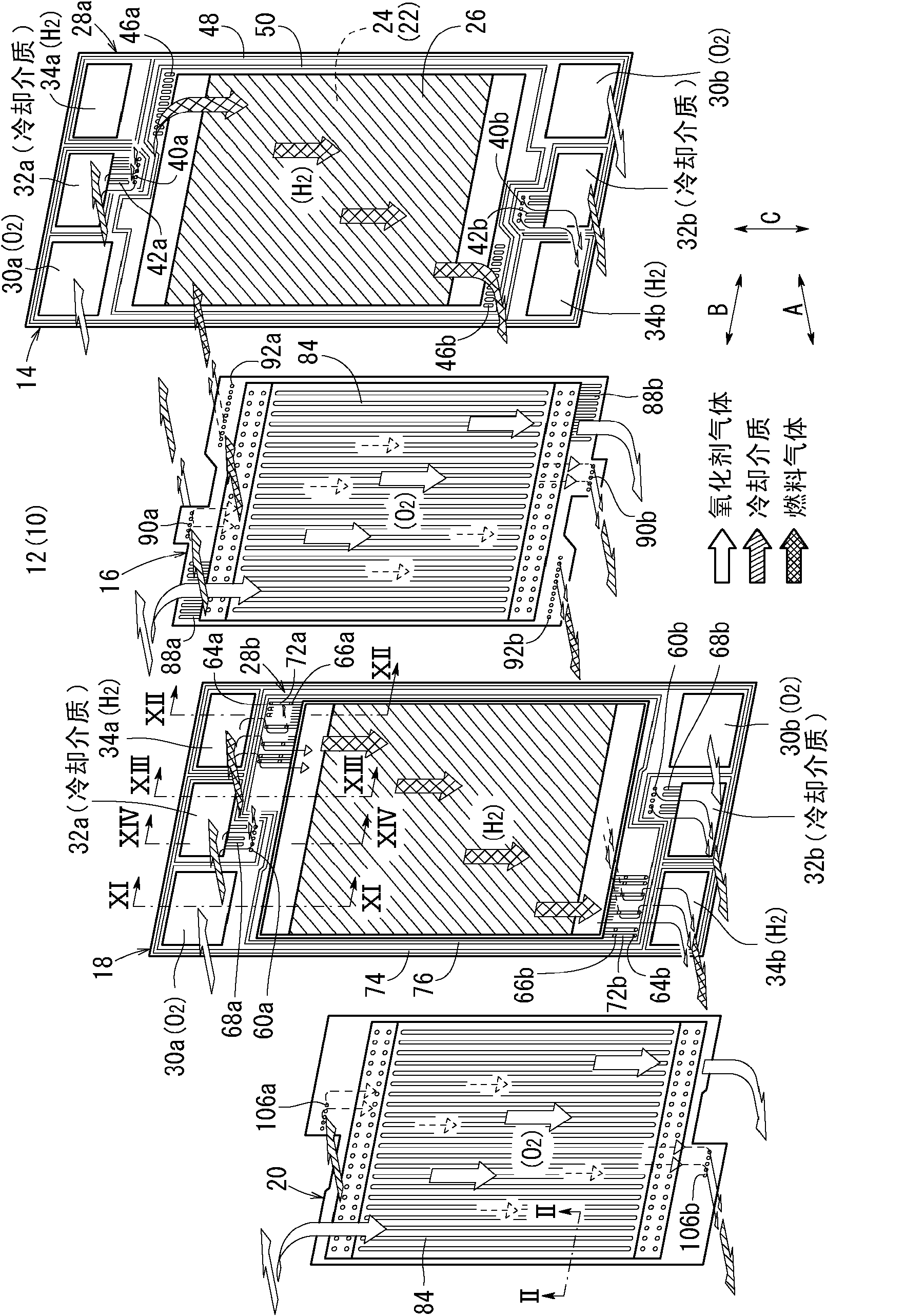
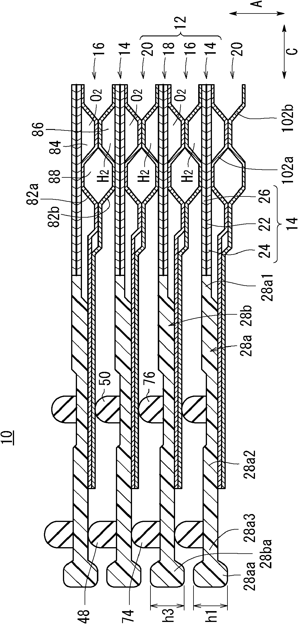
[0061] like figure 1 and figure 2 As shown, the fuel cell 10 according to the first embodiment of the present invention is constituted by stacking a plurality of battery cells 12 in the direction of arrow A (horizontal direction).

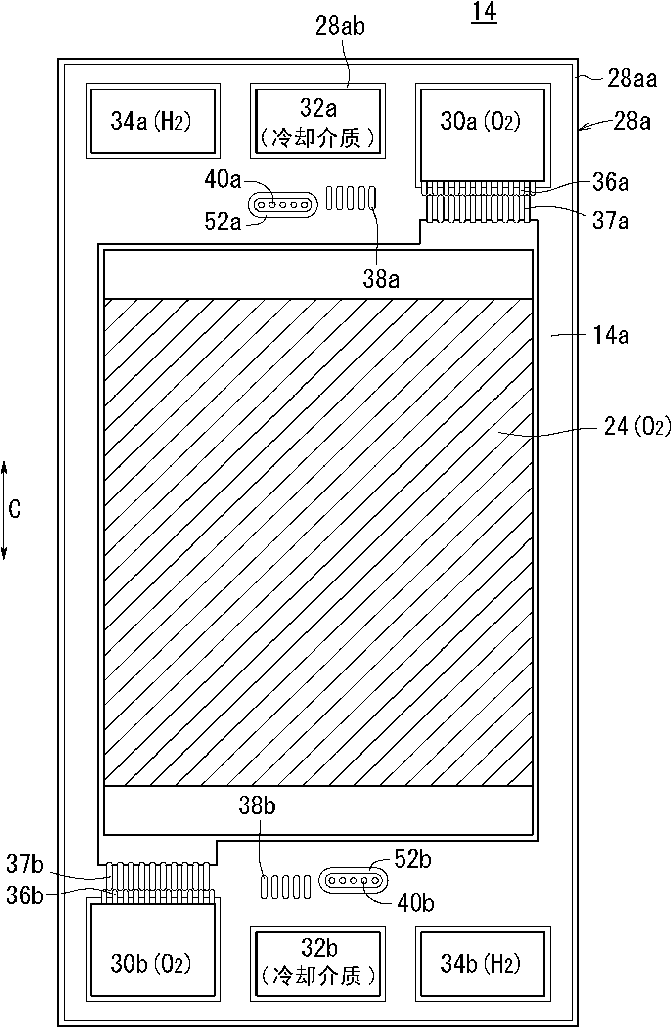
[0062] The battery cell 12 includes a first electrolyte membrane-electrode structure (electrolyte-electrode structure) (MEA) 14, a first separator 16, a second electrolyte membrane-electrode structure (electrolyte-electrode structure) (MEA) 18, and The second separator 20 . By stacking the battery cells 12, the first electrolyte membrane-electrode structure 14 is sandwiched by the second and first separators 20, 16, and the second electrolyte membrane-electrode structure 18 is sandwiched by the first and second separators. 16, 20 clamping.

[0063]The first electrolyte membrane-electrode structure 14 and the second electrolyte membrane-electrode structure 18 respectively include, for example, a solid polymer electrolyte membrane (electrolyte) ...


PUM


Abstract

The invention provides a furl cell wherein relatively expensive separators may be favorably miniaturized and the manufacturing cost may be reduced, and the stiffness of membrane-electrode assemblies may be effectively increased. The fuel cell (10) includes a cell unit (12) which includes a first membrane-electrode assembly (14), a first separator (16), a second membrane-electrode assembly (18), and a second separator (20). The first and second membrane-electrode assemblies (14, 18) are provided with frame members (28a, 28b), and fluid communication holes are provided in the stacking direction in each of the frame members (28a, 28b) provided with thickened portions (28aa, 28ba) around outer peripheral edges. The thicknesses of thickened portions (28aa, 28ba) are the largest dimensions among those of other regions along the respective outer peripheral edges excluding the outer peripheral edges.

Description

technical field [0001] The present invention relates to a fuel cell including a battery cell in which an electrolyte-electrode structure is sandwiched between a first separator and a second separator. The electrolyte-electrode structure has a pair of electrodes arranged on both sides of an electrolyte. Background technique [0002] For example, a solid polymer fuel cell uses a solid polymer electrolyte membrane composed of a polymer ion exchange membrane. In this fuel cell, a unit cell is constituted by sandwiching an electrolyte membrane-electrode structure (electrolyte-electrode structure) (hereinafter also referred to as MEA) by separators (two-way plates), and the electrolyte membrane-electrode structure is in a solid state. An anode-side electrode and a cathode-side electrode composed of an electrode catalyst layer and porous carbon are arranged on both sides of the polymer electrolyte membrane, respectively. Generally, a fuel cell stack obtained by laminating a predet...

Claims


Application Information

Patent Timeline
IPC IPC(8): H01M8/02
CPCH01M8/0273H01M8/242Y02E60/50H01M8/0267H01M8/2483Y02P70/50
Inventor 杉浦诚治小此木泰介
Owner HONDA MOTOR CO LTD
Learn More