Eureka AIR delivers breakthrough ideas for toughest innovation challenges, trusted by R&D personnel around the world.

Convex aspheric optical element surface type detection device

An optical element, surface detection technology, applied in the direction of using optical devices, measuring devices, instruments, etc., can solve the problems of inability to accurately measure the surface of convex aspheric optical components, and inability to ensure that the surface to be measured is perpendicular to the light source, etc. Simple structure, high positioning accuracy, and the effect of reducing positioning errors

Inactive Publication Date: 2012-07-18
XIAMEN UNIV
View PDF7 Cites 9 Cited by
  • Summary
  • Abstract
  • Description
  • Claims
  • Application Information

AI Technical Summary

Problems solved by technology

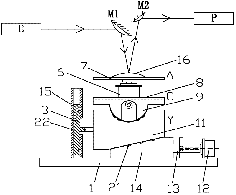
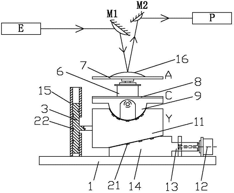
[0007] The purpose of the present invention is to solve the problem that the existing detection device cannot ensure that the surface to be measured of the workpiece is perpendicular to the light source when measuring the convex aspheric optical element, and cannot perform comprehensive and accurate measurement of the surface shape of the convex aspheric optical element. Through the A, C, Y three-axis linkage adjustment of the position and attitude of the workpiece, it is guaranteed to be able to detect the surface type detection device of the convex aspheric optical element of the entire convex aspheric surface type

Method used


Image

  • Convex aspheric optical element surface type detection device
  • Convex aspheric optical element surface type detection device
  • Convex aspheric optical element surface type detection device

Examples


Embodiment Construction

[0021] The following embodiments will further illustrate the technical solution of the present invention in conjunction with the accompanying drawings.

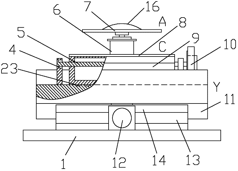
[0022] Such as figure 1 , 2 As shown, the embodiment of the present invention is provided with a light source E, a reflector M1, a receiver mirror M2, a detection platform, a lifting platform 11 and an analysis and processing system P. Among them, the detection platform is equipped with three parts: vertical motion mechanism, swing mechanism and rotary mechanism.

[0023] The vertical motion mechanism is provided with a base 1 , a first support oil chamber 21 , a lifting rod 3 , a screw motor 12 , a connecting plate 13 , a trimming wedge 14 and a limit groove 15 . The fine-tuning wedge 14 is located on the base 1, the connecting plate 13 is fixed on the fine-tuning wedge 14, and the connecting plate 13 is connected with the screw motor 12 through a ball screw. Lifting platform 11 is supported by fine-tuning wedges 14, and ...


PUM


Abstract

The invention provides a convex aspheric optical element surface type detection device, relating to an optical element detection device. The convex aspheric optical element surface type detection device is provided with a light source, a reflecting mirror, a receiving mirror, a detection platform, a lifting platform and an analytical processing system, wherein the reflecting mirror is arranged in front of the light beam of the light source, the detection platform is arranged in front of the reflecting mirror, the receiving mirror is arranged in front of an optical element, and the analytic processing system is arranged in front of the receiving mirror; the detection platform is sequentially provided with a vertical moving mechanism, a swinging mechanism and a revolving mechanism from bottom to top; the vertical moving mechanism is provided with a base, a first bearing oil chamber, a lifting rod, a lead screw motor, a connecting plate, a fine tuning wedge block and a limit slot; the swinging mechanism is provided with a third bearing oil chamber, a static pressure thrust bearing, a rotating shaft, a C-shaft operating platform, a swinging platform and a servo motor; and the revolving mechanism is provided with a motor and an A-shaft operation platform. The convex aspheric optical element surface type detection device provided by the invention has a simple structure, no mechanical efficiency loss and high output torque, and high positioning accuracy, high dynamic response and low noise can be realized. The convex aspheric optical element surface type detection device provided by the invention has the characteristics of high bearing capacity, high rotary precision, long service life and small homogenization error.

Description

technical field [0001] The invention relates to a detection device for an optical element, in particular to a surface type detection device for a convex aspherical optical element. Background technique [0002] Aspheric optical components have many advantages in application, especially in recent years, the emergence of new materials and the development of new manufacturing technology have made the aspheric processing technology develop by leaps and bounds. However, the manufacture of aspheric components must be combined with accurate aspheric surface detection technology to obtain qualified aspheric surfaces. Therefore, the detection of aspheric optical components has become the frontier field of optical measurement technology research. [0003] At present, most of the methods for detecting aspheric surfaces are contact and non-contact measurement methods, but there are usually some troubles in non-contact measurement. In non-contact measurement, since the geometric shape ...

Claims


Application Information

Patent Timeline
IPC IPC(8): G01B11/24
Inventor 彭云峰林建华郭隐彪董之然白志扬
Owner XIAMEN UNIV
Why Eureka
Eureka Blog
Learn More