Contact type temperature non-inductive three-dimensional detection sensor based on fiber Bragg grating (FBG)
A fiber Bragg, three-dimensional detection technology, applied in instruments, measuring devices, optical devices, etc., can solve the problems of difficult to achieve precise online measurement, two-dimensional measurement errors, inability to separate, etc., to meet the requirements of industrial high-speed measurement, improve The effect of adaptability, simple data processing
- Summary
- Abstract
- Description
- Claims
- Application Information
AI Technical Summary
Problems solved by technology
Method used
Image
Examples
Embodiment 1
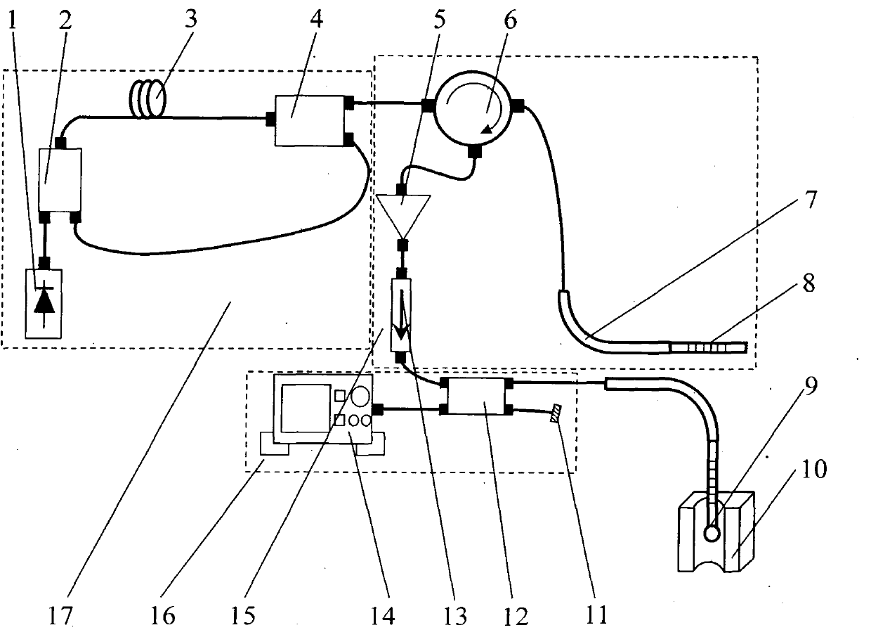
[0040] A contact-type temperature-insensitive three-dimensional detection sensor based on fiber Bragg gratings is composed of a broadband light source system 17, a temperature compensation system 15, a probe 9 and a signal receiving system 16; the broadband light source system 17 includes a pump laser 1, a WDM Coupler 2, erbium-doped fiber 3 and beam splitter 4, the two ends of erbium-doped fiber 3 are respectively connected with WDM coupler 2 and beam splitter 4, and the optical fiber connects pump laser 1 with WDM coupler 2 and WDM coupler respectively 2 communicates with the beam splitter 4; the signal receiving system 16 is composed of a spectrum analyzer 14, a fiber coupler 12 and a refractive index matching liquid 11, and the optical fiber connects the spectrum analyzer 14 with the fiber coupler 12, the fiber coupler 12 and the refraction The rate matching liquid 11 communicates; EDFA5, the first circulator 6, the guide tube 7, the reference FBG8, and the optical fiber bl...
Embodiment 2
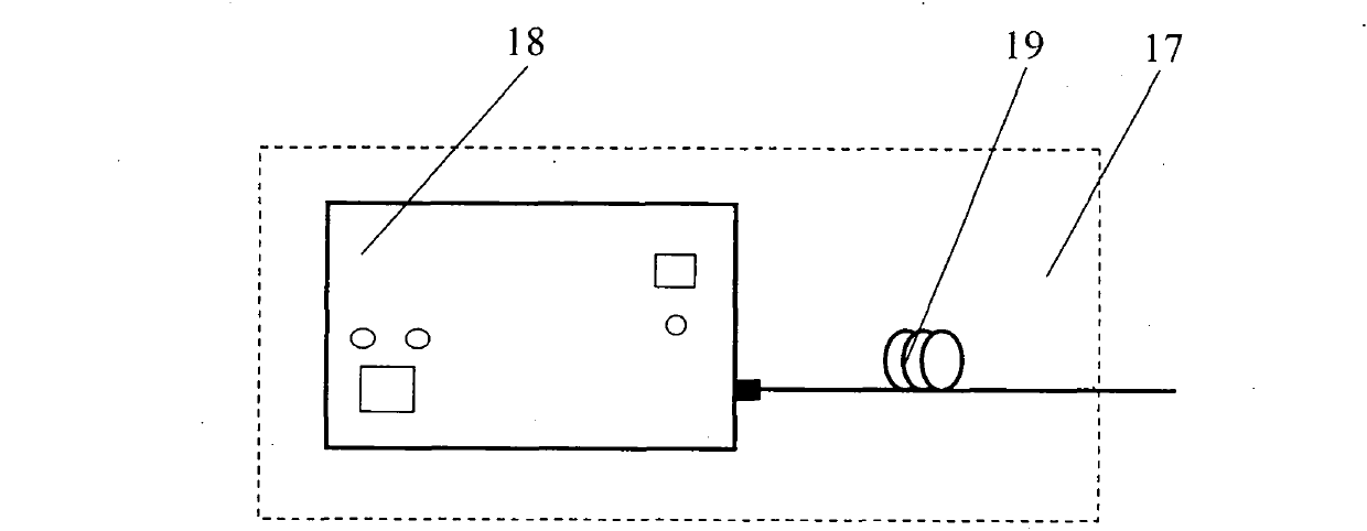
[0045] The broadband light source system 17 is composed of a broadband light source 18 connected to an erbium-doped optical fiber 19. The broadband light source 18 directly generates a broadband light beam, which enters subsequent systems through the erbium-doped optical fiber 19. Other components and working principles of this embodiment are the same as those of Embodiment 1.
Embodiment 3
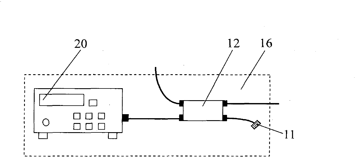
[0047] The signal receiving system 16 is composed of an optical power meter 20 , a fiber coupler 12 and a refractive index matching liquid 11 , and the light reflected by the FBG in the probe 9 is received by the optical power meter 20 . When the end of the probe 9 touches the sidewall of the microhole 10 to be tested, it will produce bending deformation (bending), which will cause the deviation of the FBG reflection center wavelength in the probe 9, but the reflection center wavelength of the reference FBG8 is constant, so The overlapping state of the reflected light spectrum of the reference FBG8 and the FBG of the probe 9 will change, and at this time the power of the returned light wave received by the optical power meter 20 will decrease rapidly, so as to sense the contact between the probe 9 and the surface to be measured. Other components and working principles of this embodiment are the same as those of Embodiment 1.
PUM
 Abstract
Description
Claims
Application Information
 - R&D
- Intellectual Property
- Life Sciences
- Materials
- Tech Scout
- Unparalleled Data Quality
- Higher Quality Content
- 60% Fewer Hallucinations
Browse by: Latest US Patents, China's latest patents, Technical Efficacy Thesaurus, Application Domain, Technology Topic, Popular Technical Reports.
© 2025 PatSnap. All rights reserved.Legal|Privacy policy|Modern Slavery Act Transparency Statement|Sitemap|About US| Contact US: help@patsnap.com


