
Jet type heat exchanger unit with two-stage-belt heat regenerator

A technology of heat exchange units and jet heat pumps, which is applied in heating methods, household heating, heating systems, etc., can solve the problems of high investment in pipeline networks, high energy consumption in pipeline network transportation, and high cost of central heating, and achieve expansion Effect of heating radius, improving heat transport capacity, improving heat utilization rate and its economy

Active Publication Date: 2012-07-18
TSINGHUA UNIV +1
View PDF3 Cites 4 Cited by
  • Summary
  • Abstract
  • Description
  • Claims
  • Application Information

AI Technical Summary

Problems solved by technology

Due to the limitation of environmental protection factors in urban areas, newly-built centralized heat sources are generally located in the suburbs far away from the urban area. higher cost

Method used


Image

  • Jet type heat exchanger unit with two-stage-belt heat regenerator
  • Jet type heat exchanger unit with two-stage-belt heat regenerator
  • Jet type heat exchanger unit with two-stage-belt heat regenerator

Examples


Embodiment 1

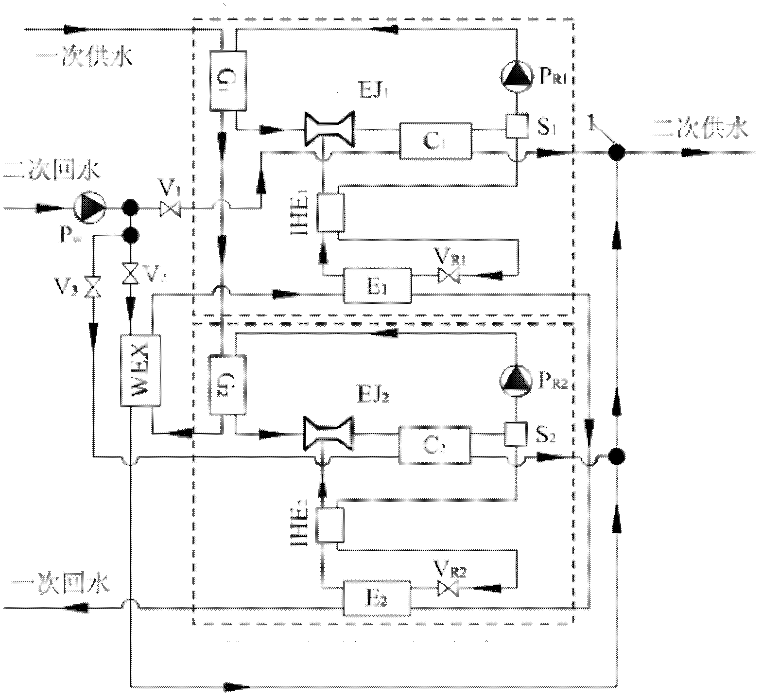
[0026] A two-stage jet heat exchange unit with regenerator, such as figure 1 As shown, the jet heat pump with regenerator in the first stage, the jet heat pump with regenerator in the second stage, the water-to-water heat exchanger WEX, the secondary side circulating water pump P w , valve V 1 , valve V 2 , valve V 3 And connecting pipelines and other accessories, the connecting pipelines include working medium system pipelines and water system pipelines, through the water system connecting pipelines, the two-stage jet heat pump and water-to-water heat exchanger WEX are brought to the heat exchanger Organically combined.

[0027] The working medium system pipeline of this embodiment: from the first liquid storage tank S 1 The liquid working fluid is divided into two paths, and the liquid working fluid in one path flows through the first working fluid circulating pump PR in turn.1 , the first generator G 1 , the first injector EJ 1 , then at the first injector EJ 1 insid...

Embodiment 2

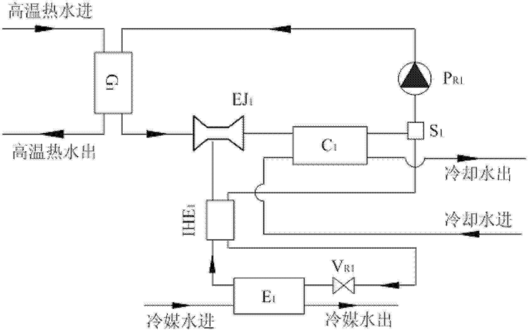
[0033] A two-stage jet heat exchange unit with regenerator, such as figure 2 As shown, the jet heat pump with regenerator in the first stage, the jet heat pump with regenerator in the second stage, the water-to-water heat exchanger WEX, the secondary side circulating water pump P w , valve V 2 , valve V 3 , connecting pipelines and other accessories, in which the connecting pipelines are composed of working fluid system pipelines and water system pipelines, and the jet heat pump and water-water heat exchanger WEX that bring the two stages to the heat exchanger through the water system connection pipelines Organically combined.

[0034] The working medium system pipeline of this embodiment: from the first liquid storage tank S 1 The liquid working fluid is divided into two paths, and the liquid working fluid in one path flows through the first working fluid circulating pump PR in turn. 1 , the first generator G 1 , the first injector EJ 1 , then at the first injector EJ ...


PUM


Abstract

The invention discloses a jet type heat exchanger unit with a two-stage-belt heat regenerator, which belongs to the technical field of energy utilization. The jet type heat exchanger unit is composed of a jet type heat pump of a first-stage-belt heat regenerator, a jet type heat pump of a second-stage-belt heat regenerator, a water-water heat exchanger, a secondary collateral circulation water pump, a valve and a connecting pipeline. The connecting pipeline consists of a working medium system pipeline and a water system pipeline, wherein the water system pipeline is divided into a primary side pipeline and a secondary side pipeline, the primary side pipeline adopts a series connection mode, and the secondary side pipeline adopts a parallel connection mode or a mixed connection mode. The jet type heat exchanger unit contributes to improvement of heat delivery capacity of a primary heat supply network and enlargement of the heat supply radius of large heat sources, and further contributes to water return and waste heat recovery of heat sources by utilizing low temperature to improve heat utilization ratio and economical efficiency of the heat sources.

Description

technical field [0001] The invention belongs to the technical field of energy utilization, and in particular relates to a two-stage jet heat exchange unit with a regenerator. Background technique [0002] With the rapid development of northern urbanization, the demand for heating load in northern cities and towns has increased dramatically. Due to the limitation of environmental protection factors in urban areas, newly-built centralized heat sources are generally located in the suburbs far away from the urban area. higher cost. In addition, with the continuous increase of urban floor area ratio, the heating area of ​​buildings in the original heating pipe network area has increased sharply, and the demand for heating load has increased sharply, which has highlighted the gap between the demand for heating in winter and the insufficient heat supply capacity of the heating network. contradictions between. The supply / return water temperature of conventional central heating te...

Claims


Application Information

Patent Timeline
IPC IPC(8): F24D3/18F24D3/10
CPCY02B30/52
Inventor 付林孙方田张世钢罗勇
Owner TSINGHUA UNIV
Learn More