
Patsnap Eureka
For R&D, Patsnap Eureka makes reading and utilizing patents & technical documents easy.
Patsnap Eureka AIR
Designed for self-driven R&D workflows. Generate viable solutions, solve complex R&D challenges, empower your innovation with AI.

Patsnap Eureka Materials
Designed for material experts only. Revolutionize your material R&D, from search, analyze, to developing new materials.

TechResearch
Generate reliable direction feasibility study reports for your R&D in just a few steps.

TechSeek
Discover and master advanced knowledge NOW. Basics, ideas, possibilities, all at once.

TechMind
As an expert in R&D Theories, TechMind can generates customized viable solutions instantly.

TechRisk
Analyze your overall solution with one click, know your potential R&D risks in advance.

TechMonitor
Get weekly tech updates, stay abreast of the latest tech innovations and key insights.
Flexible flywheel assembly
A flexible flywheel and assembly technology, applied in the field of flywheels, can solve the problems of complex flywheel structure, low material utilization rate, and difficult manufacturing, and achieve the effects of saving labor and energy, high material utilization rate, and low production cost
- Summary
- Abstract
- Description
- Claims
- Application Information
AI Technical Summary
Problems solved by technology
Method used
Image

Examples
Embodiment Construction
[0019] The technical solutions of the present invention will be further described in detail below in conjunction with the accompanying drawings and specific embodiments.
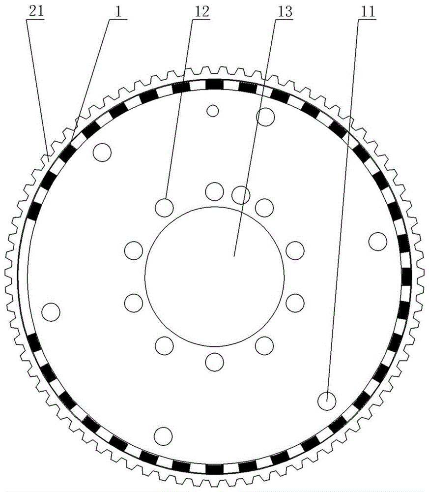
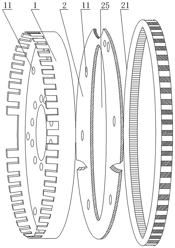
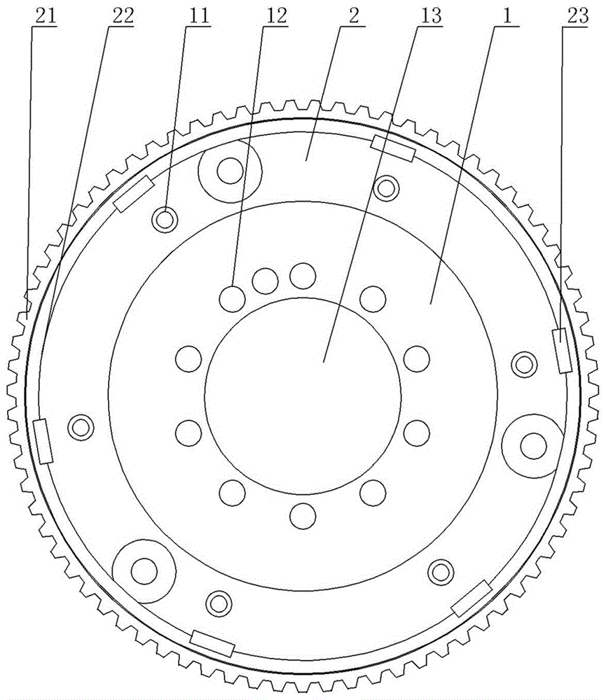
[0020] figure 1 It is a structural representation of the present invention. Depend on figure 1 combine figure 2 , 3 It can be seen that the flexible flywheel disc assembly is mainly composed of the signal disc 1 , the connection disc 2 , the flywheel ring gear 21 and the like. The thickness of the signal plate 1 is 2.5mm, and the thickness of the connection plate 2 is 3mm. The connection plate 2 and the signal plate 1 are respectively provided with 6 corresponding riveting holes 11 . The signal plate 1 and the connecting plate 2 are riveted together, and the bottom side wall of the connecting plate 2 is welded together with the ring gear 21 .
[0021] In order to reduce the stress after the connecting pad 2 and the signal pad 1 are recombined, the connecting pad is designed in a ring shape, and the dia...
PUM
 Abstract
Description
Claims
Application Information
 - R&D Engineer
- R&D Manager
- IP Professional
- Industry Leading Data Capabilities
- Powerful AI technology
- Patent DNA Extraction
Browse by: Latest US Patents, China's latest patents, Technical Efficacy Thesaurus, Application Domain, Technology Topic, Popular Technical Reports.
© 2024 PatSnap. All rights reserved.Legal|Privacy policy|Modern Slavery Act Transparency Statement|Sitemap|About US| Contact US: help@patsnap.com